
Introduction
Welcome to the AutoBRIDGE User Manual!
Welcome to AutoBRIDGE – your indispensable tool for revolutionizing infrastructure modeling within Autodesk Revit! Empowering engineers and designers with unparalleled capabilities, AutoBRIDGE simplifies complex tasks such as corridor creation, instance array generation, girder modeling, and more, with intuitive controls and precise customization options.
Explore the key features that make AutoBRIDGE a must-have tool for infrastructure automation, and learn how to leverage its capabilities to streamline your modeling process and achieve exceptional results.
Before we proceed further, it’s essential to familiarize ourselves with the comprehensive AutoBRIDGE User Manual. This manual serves as your ultimate guide to harnessing the full potential of AutoBRIDGE, providing step-by-step instructions, detailed explanations, and invaluable insights to help you navigate through the intricacies of infrastructure modeling within Autodesk Revit.
Additionally, for more in-depth explanations and visual demonstrations, we offer video tutorials. These videos are available on our websit. Whether you prefer written instructions or visual demonstrations, we have resources available to suit your learning preferences and help you maximize your AutoBRIDGE experience.
About AutoBRIDGE
AutoBRIDGE aims to revolutionize the way engineers and designers create 3D infrastructure elements within the Autodesk Revit add-in.
With a passion for simplifying complex tasks and a commitment to delivering exceptional tools, the AutoBRIDGE team has crafted a solution to address the specific needs and challenges faced by infrastructure professionals. AutoBRIDGE empowers users to streamline their 3D modeling process, enhance BIM collaboration, and achieve outstanding results.
Driven by a vision of advancing 3D modeling of infrastructure design and automation, the AutoBRIDGE team continues to innovate and refine the software, ensuring it remains at the forefront of the industry. By staying responsive to user feedback and evolving alongside the latest advancements in technology, AutoBRIDGE remains a trusted companion for engineers and designers worldwide.
Let’s embark on this exciting journey together and elevate your design experience with AutoBRIDGE!
Key Features
Corridor Creation
Corridor Creation is the first feature of the AutoBRIDGE add-in, it’s designed to expedite the creation of corridors by integrating with Civil 3D alignment data. Users can define alignment, select Revit nested families, set solid and void parameters, and execute corridor creation accurately. More detailed instructions and best practices are provided here.Instance Array
This feature provides users with the capability to efficiently generate arrays of instance elements within Revit, accommodating a variety of family types such as Structural Column, Structural Framing, and Generic. The integration with Civil 3D alignment data is a key aspect of this feature, playing a pivotal role in guaranteeing precise placement of elements.Grider Modeling
Grider modeling enables users to model structural framing elements, specifically bridge girders, using model lines and bridge decks. This feature ensures a straightforward process for attaching girders to the bottom of the deck.Family Manager
The Family Manager feature is designed to enhance efficiency by allowing users to add templates for AutoBRIDGE. This ensures the automatic saving of templates in the add-in, promoting the reuse of nested families across various projects and preventing duplication of work.Variation Parameters Control
This feature provides engineers with precise control over both vertical and horizontal variation parameters. This feature allows for the management of intricate design elements, such as the top of retaining walls or the soffit of bridge decks, using fixed levels, Civil 3D alignment profiles, and 3D polylines. More detailed instructions and best practices are provided here.Superelevation Management
The final feature of the AutoBRIDGE system is the Superelevation Management. This feature allows engineers to control superelevation in road elements efficiently, either by importing information from Civil 3D or any platform or manually inputting superelevation designs using grids.Getting Started
Before diving into the functionalities of AutoBRIDGE, it’s essential to familiarize yourself with the basics. This section will guide you through the initial setup process and provide an overview of the system’s interface and navigation.
AutoBRIDGE Setup
1. Installation Process
Step 1: License Agreement
- After launching the installer, you will be presented with the “AutoBRIDGE 2024 License Agreement” (see screenshot).
- Read through the terms and conditions carefully.
- To proceed, check the box labeled “I agree to the License terms and conditions” and click “Next.”
(Refer to Screenshot S1)

Step 2: Confirm Installation
- The next screen will confirm that you’re about to install AutoBRIDGE 2024.
- Click the “Install” button to begin the installation.
(Refer to Screenshot S2)

Step 3: Installation Complete
- Once the installation is complete, you will see a confirmation screen.
- Click “Finish” to close the installer.
(Refer to Screenshot S3)

2. Accessing AutoBRIDGE in Revit
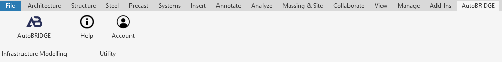
- After installation, open Autodesk Revit.
- You should see the AutoBRIDGE tab added to the Revit toolbar, under “Infrastructure Modelling,” where you can access features like Help, Account, and Utilities.
(Refer to Screenshot S4)
Creating a User Account
To access AutoBRIDGE, you need to create a user account. Follow these steps:
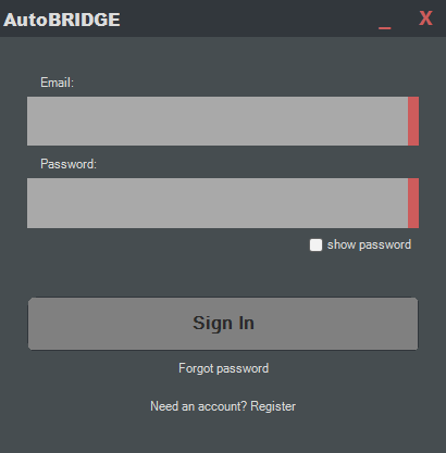
1. Sign-In Window
- When you launch AutoBRIDGE for the first time, the sign-in window will appear.
- Enter your email and password to log in, or click “Register” if you’re a new user.
(Refer to Screenshot S5)
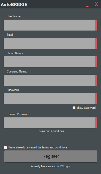
2. Registration Form
- Fill out the registration form with the required details: Username, Email, Phone Number, Company Name, Password, and Confirm Password.
- Accept the Terms and Conditions by checking the box.
- Click “Register” to create your account.
(Refer to Screenshot S6)
AutoBRIDGE Interface Overview
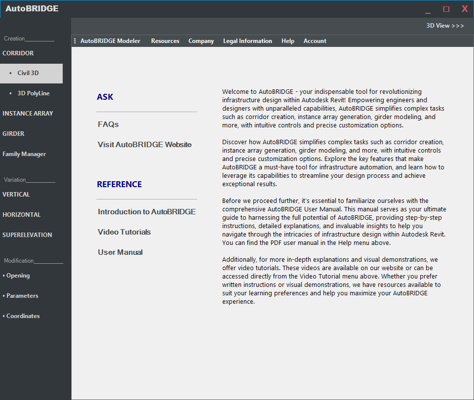
Once signed in, you will have access to the full AutoBRIDGE interface. Key features are located on the left sidebar, categorized under Creation, Variation, and Modification sections, allowing you to model infrastructure elements efficiently.
(Refer to Screenshot S7)
Accessing AutoBRIDGE in Revit
- Congratulations! You’ve successfully installed AutoBRIDGE and are ready to streamline your 3D infrastructure modeling process.
- Feel free to reach out if you encounter any issues during installation or if you have further questions about accessing AutoBRIDGE in Revit. Happy modeling!
AutoBRIDGE Features
Creation
Corridor Creation
Now that you’ve familiarized yourself with the basics, let’s explore the key features and functionalities of AutoBRIDGE. This section will provide you with detailed instructions on how to perform various tasks and utilize the Add-in’s capabilities to their fullest potential.
Civil 3D
This feature enables the creation of a corridor Element in Revit using the alignment data directly from the active Civil 3D Document.
- Open the Civil 3d panel within corridor creation feature, by opening this panel you find exactly 3 tabs:
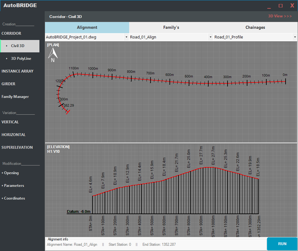
Alignment Section: (Choose the Document, Alignment, and Profile)
In this step, you are prompted to select the specific document, alignment, and profile for your corridor. This ensures that your corridor is aligned with the relevant design elements, Refer to “Figure 1 – alignment tab” for visual guidance.Important Preparations:
Ensure the Civil 3D document is active before proceeding.
Acquire Shared Coordinates in Revit: To maintain consistency between Revit and Civil 3D, ensure Revit acquires the shared coordinates from the Civil 3D file. This alignment of Revit’s coordinate system with Civil 3D’s shared coordinates ensures that your corridor elements are positioned precisely within the overall project layout.
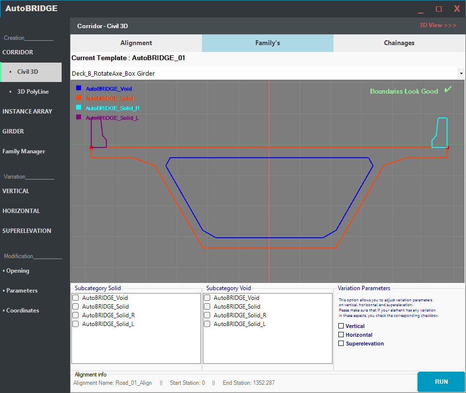
Family Section: (Select the Revit Nested Family)
- Choose a Revit Nested Family: Select a nested family that fits your corridor design. This could include elements like bridges, decks, walls, tunnels, or other structural components.
- Define Solid and Void: Specify which parts of the selected family should be treated as solid and which should be void.
- Set Variation Parameters: If your design requires variations such as vertical, horizontal, or superelevation adjustments, check the corresponding box in the Variation Parameters section. Refer to Figure 2 – Family Section for visual guidance.
- Chainages Section:
- Input Chainages: Provide the necessary chainages in rows, specifying the distances along the alignment where design changes occur. This ensures accurate placement of corridor elements. Refer to “Figure 3” for visual guidance.

5. Execute Corridor Creation:
- After configuring the parameters, press the Run button to execute the corridor creation process and generate the corridor according to your Refer to Figure 4.

3D PolyLine
This feature enables the creation of a corridor Element in Revit using importing 3D polyline from AutoCAD Document.
- Open the 3D polyline panel within corridor creation feature, by opening this panel you find exactly 3 tabs:
- Alignment Section: (Choose the AutoCAD layer and specify polyline length)
- Choose the AutoCAD layer associated with the 3D polyline.
- Specify the polyline length, ensuring accurate representation in the corridor. Refer to “Figure 5 – alignment tab” for visual guidance.

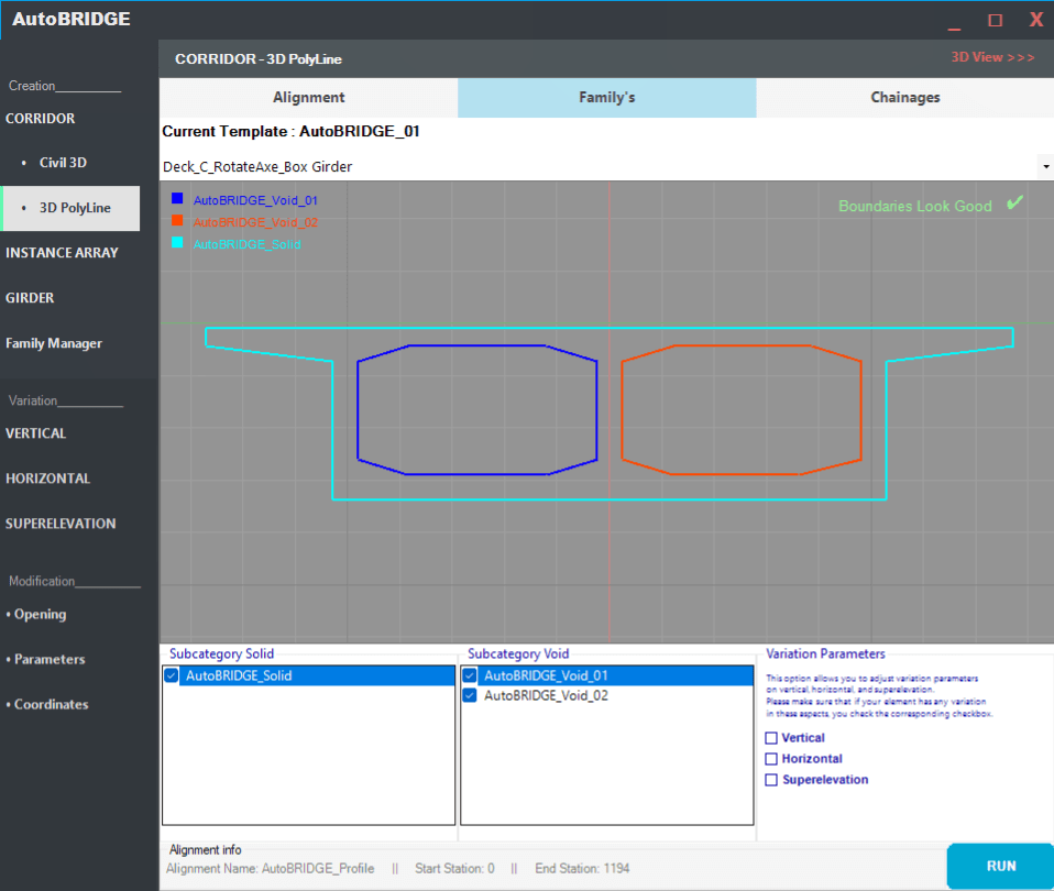
Family Section: (Select the Revit Nested Family)
- Choose a Revit Nested Family: Select a nested family that fits your corridor design. This could include elements like bridges, decks, walls, tunnels, or other structural components.
- Define Solid and Void: Specify which parts of the selected family should be treated as solid and which should be void.
- Set Variation Parameters: If your design requires variations such as vertical, horizontal, or superelevation adjustments, check the corresponding box in the Variation Parameters section. Refer to Figure 6 – Family Section for visual guidance.
Chainages Section:
- Input Chainages Manually: Provide the necessary chainages in rows, specifying the distances along the alignment where design changes occur. This ensures accurate placement of corridor elements. Refer to Figure 7


- Lines Option: Alternatively, choose the “Lines” option to select a group of model lines. This allows you to define chainages using the points where these model lines intersect with the 3D polyline alignment. Refer to Figure 8
Instance Array Creation
The Instance Array feature in AutoBRIDGE allows users to efficiently generate array of instance elements within Revit, accommodating various family types such as: Structural Column, Structural Framing, and generic elements. This feature integrates seamlessly with Civil 3D alignment data, ensuring precise placement of elements
Civil 3D Integration
This feature enables the creation of an instance array in Revit using the alignment data directly from the active Civil 3D Document.
Follow the detailed steps below to utilize the instance array feature:
- Open the Instance Array Panel:
- Navigate to the AutoBRIDGE tab in Revit.
- Click on the “Instance Array/ Civil 3D” button to open the panel.
- Alignment Section: (Choose the Document, Alignment, and Profile)
- Choose the document: Select the Civil 3D document containing the alignment data.
- Select Alignment and Profile: Choose the specific alignment and profile for the array. This ensures that your Instance Array is aligned with the relevant design elements. Refer to “Figure 10″ the guide for visual assistance.

- Family Section: (Choose the Document, Alignment, and Profile)
- Select the Revit Family:
- For Structural Column Family Type Grid:
- Select the column type.
- Define the X, Y Top, Y Bottom, and Rotation parameters.
- For Structural Framing Family Type Grid:
- Select the framing type.
- Define the X First, Y First, X End, and Y End parameters.
- For Generic Family Type Grid:
- Select the generic family type.
- Define the X, Y, and Rotation parameters.
- For Structural Column Family Type Grid:
- Chainages Section: (Choose the Document, Alignment, and Profile)
- Input the Chainages in row, Refer to “Figure 11 instance array civil 3d chainages section” for visual guidance:
- Execute Instance Array Creation:
After configuring the parameters, press the Run button to execute the instance array creation process, and generate the corridor according to your specifications.
- Select the Revit Family:

3D Polyline
This feature enables the creation of an instance array in Revit using importing 3D polyline from AutoCAD Document
Follow the detailed steps below to utilize the instance array feature:
- Open the Instance Array Panel:
- Navigate to the AutoBRIDGE tab in Revit.
- Click on the “Instance Array/ 3D Polyline” button to open the panel.
- Alignment Section: (Choose the AutoCAD layer and specify polyline length)
- Choose the AutoCAD layer associated with the 3D polyline.
- Specify the polyline length, ensuring accurate representation in the corridor. Refer to “Figure 12 – alignment tab” for visual guidance.

- Family Section: (Choose the Document, Alignment, and Profile)
- Select the Revit Family:
- For Structural Column Family Type Grid:
- Select the column type.
- Define the X, Y Top, Y Bottom, and Rotation parameters.
- For Structural Framing Family Type Grid:
- Select the framing type.
- Define the X First, Y First, X End, and Y End parameters.
- For Generic Family Type Grid:
- Select the generic family type.
- Define the X, Y, and Rotation parameters.
- For Structural Column Family Type Grid:
- Chainages Section: (Choose the Document, Alignment, and Profile)
- Input the Chainages in row, Refer to “Figure 13 instance array civil 3d chainages section” for visual guidance:
- Execute Instance Array Creation:
After configuring the parameters, press the Run button to execute the instance array creation process, and generate the corridor according to your specifications.
- Select the Revit Family:

Girder Modeling
The Girder Modeling feature in AutoBRIDGE simplifies the creation of structural framing elements, specifically bridge girders, within Autodesk Revit.
By utilizing model lines and bridge decks, engineers can efficiently attach girders to the bottom of the deck, streamlining the modeling process.
Please note that: AutoBRIDGE will generate the girders and attach them to the designated position at the bottom of the deck.
Model Line
Follow these steps to leverage the Girder Modeling feature effectively:
- Initiate Girder Creation:
Click on the “Model Line” button located under the Grid section on the AutoBRIDGE Main Toolbar to initiate the girder creation process.
- Select Components
Choose the appropriate components required for girder modeling, including the deck family, model line group and the desired girder type.
This selection ensures compatibility and accuracy in the girder design.
- Execute Girder Creation
Once the components are selected and configured, press the Run button to execute the girder creation process.

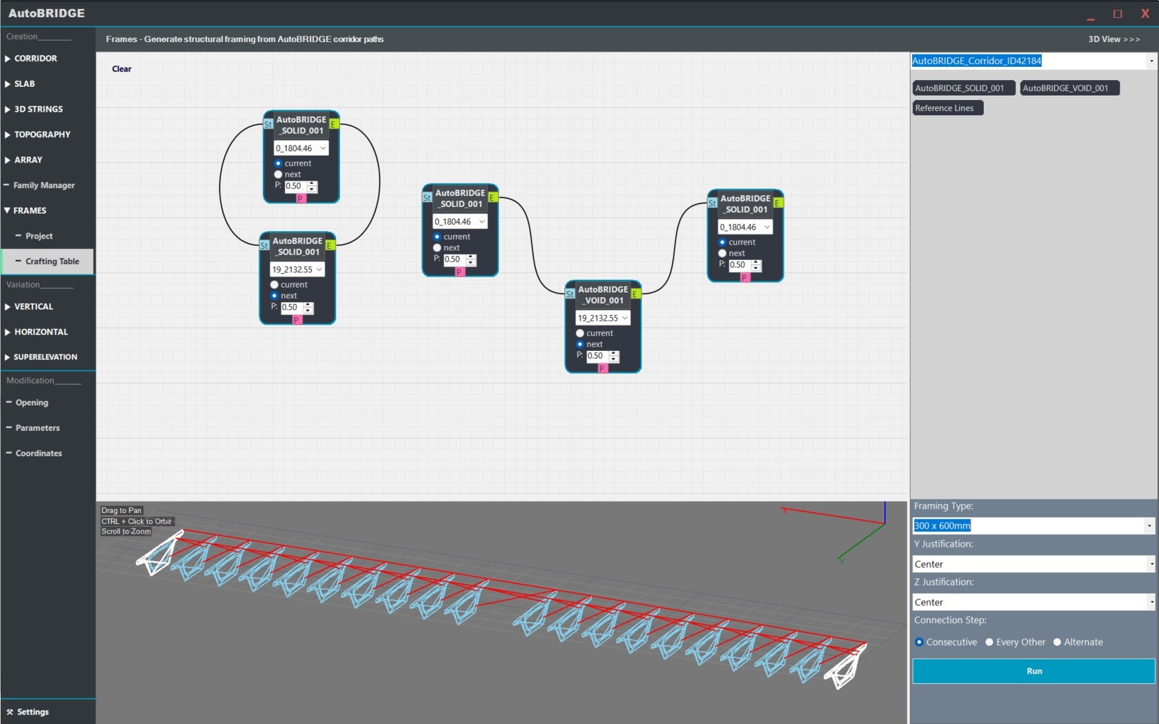
Crafting Table
-
-
-
Crafting Table Interface Overview
-
-
-
Feature: Navigating the three main functional areas of the visual editor.
- The Canvas (Top Left): Your primary workspace where you drop, organize, and connect logic nodes to define framing rules.
- 3D Preview (Bottom Left): A real-time visualization tool to verify your geometry and node connections before modeling in Revit.
- Control Panel (Right): Global settings for Revit families, beam justification, and the execution “Run” button.
-
-
-
Working with Nodes
-
-
-
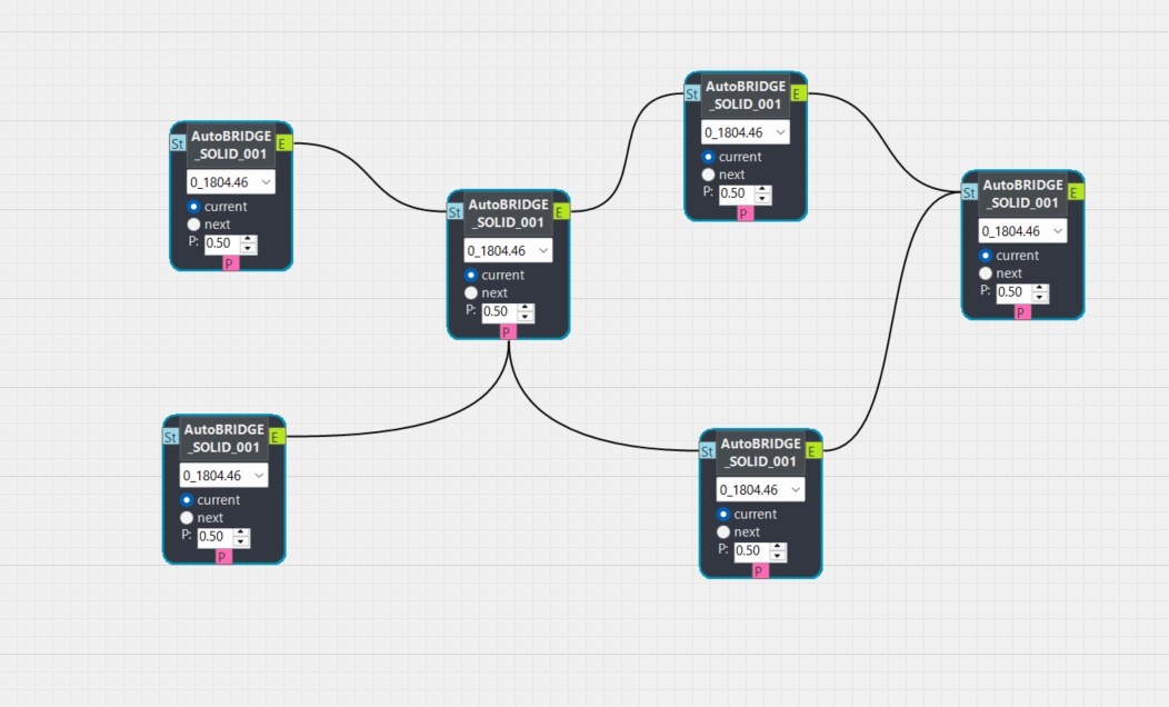
Problem: Understanding how to create and configure individual nodes.
- Solution: Select a subcategory from the sidebar list to generate a corresponding node on the canvas representing a corridor curve.
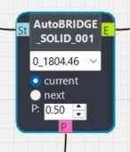
- Solution: Use the Station Selector to set the specific station index and toggle the Station Logic between “Current” and “Next” for diagonal spans.
- Solution: Adjust the Parameter (P) value (0.0 to 1.0) to pin a point specifically anywhere along the subcategory curve’s length.
- Solution: Manage nodes efficiently using standard shortcuts: Drag to move, CTRL+C to copy, CTRL+V to paste, and Delete to remove.
-
-
-
Establishing Connections & Logic
-
-
-
Problem: Creating beams between different points on the corridor.
- Solution: Click and drag from a node’s anchor points (Start, End, or P) to another node’s anchor point to create a logic link.
- Solution: For cross-bracing, connect a node set to “Current” station to a node set to “Next” station.
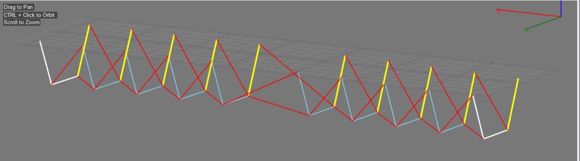
- Solution: Verify connections via the visual feedback; links appear as Bezier curves on the canvas and white lines in the 3D Preview window.
-
-
-
3D Preview Navigation
-
-
-
Problem: Difficulty inspecting the model logic before running the automation.
- Solution: Use CTRL + Left Click and drag to orbit the camera around your framing logic.
- Solution: Use the Middle Mouse Button (scroll wheel) drag to pan the view, and rotate the wheel to zoom in and out.
- Solution: Double-click anywhere within the 3D window to trigger a “Zoom Fit,” centering the entire model in your view.
-
-
-
Framing Settings & Model Generation
-
-
-
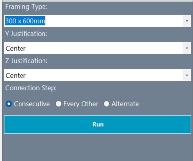
Problem: Beams not appearing with the correct family or alignment in Revit.
- Solution: Ensure the correct Revit Structural Framing family symbol is selected in the right-hand Control Panel before clicking Run.
- Solution: Set Y and Z Justification (Top, Center, Bottom, etc.) to ensure the beam sits correctly relative to the corridor curves.
- Solution: Choose the appropriate Connection Step; use “Consecutive” for every station or “Every Other” to create spaced-out framing.
- Solution: Finalize the process by clicking “Run”; AutoBRIDGE will open a transaction and generate native Revit elements based on your visual map.
-
-
-
Troubleshooting & Performance
-
-
-
Problem: The editor is lagging or connections are not producing the expected results.
- Solution: Use CTRL + Z to undo the last action on the canvas if a connection was made in error.
- Solution: Use the Selection Box (click and drag on canvas empty space) to select multiple nodes for batch movement and organization.
- Solution: If the 3D Preview does not update, ensure all nodes have a valid Station Index assigned.
- Solution: Regularly save your Revit project before running complex “Crafting Table” transactions involving hundreds of elements.
-
-
-
-
Family Manager
The Family Manager is a core component of AutoBRIDGE that streamlines the creation, management, and application of bridge templates and nested families within your Revit projects.
This feature is designed to enhance productivity by allowing you to efficiently reuse predefined bridge elements, reducing the need for repetitive work.
Key Functions:
- Template Management
Easily add and save custom bridge templates within AutoBRIDGE. Once a template is created, it is stored within the add-in for future use across any number of projects.
- Nested Family Integration
Incorporate any number of nested families into your template. Nested families are complex Revit families that contain other families, which are essential for detailed bridge modelling.
Project Efficiency
By utilizing the Family Manager, you can ensure consistent bridge design elements are used throughout your projects, which not only saves time but also maintains design integrity.
Interface Overview:
- Current Template List
Located at the top of the Family Manager, this Template List allows you to select from existing templates or to create a new one. This current template in use is displayed here.
Graphical Display Area
The central part of the Family Manager shows a graphical representation of the selected bridge template’s profile. This visual aid helps you understand spatial relationships.
Usage:
- Selecting a template
Use the Current Template dropdown menu to choose an existing template or create a new one for your bridge design.
- Adding Nested Families
To add a nested family to the selected template, use the Nested Family list to select the desired elements and Click Add. These families will be associated with the template for future use.
- Template List
View all available templates in the Templates list. You can create new templates, delete, unnecessary ones, or set a selected template as the current working template.
- Graphical Representation
The central display area provides a visual representation of the bridge profile associated with the selected template, allowing for immediate visual feedback as you manage and edit bridge components.
- Boundary Validation
- The Boundary Validation Successful message indicates that the defined boundaries for the bridge components are correctly set, ensuring that the elements will fit within the project constraints.
By leveraging the Family Manager, you can significantly reduce the time spend on repetitive tasks, allowing you to focus on the more critical aspects of bridge design and engineering.

Variation
Within AutoBRIDGE, variation management serves as a cornerstone of infrastructure design, offering comprehensive control over both vertical and horizontal parameters as well as superelevation.
Vertical Variation
The vertical variation feature in AutoBRIDGE offers precise control over all vertical parameters within an element. It enables adjustment such as the top of retaining walls or the soffit of bridge decks.
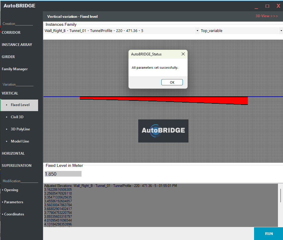
Fixed Level
This functionality allows for the centralized control of all vertical parameters within a single global level. To utilize this feature:
- Select the desired family name.
- Choose the parameter name.
- Specify the fixed level in meters.
- Press Run to execute the process.
Refer to “Figure 16 – fixed level” for visual guidance.
Civil 3D
This feature allows you to control the vertical variation parameter from Civil 3D alignment profile:
- Select family name.
- Choose the parameter name.
- Select the document, alignment, and profile.
- Press Run to execute the process.
Refer to “Figure 17 – fixed level” for visual guidance.

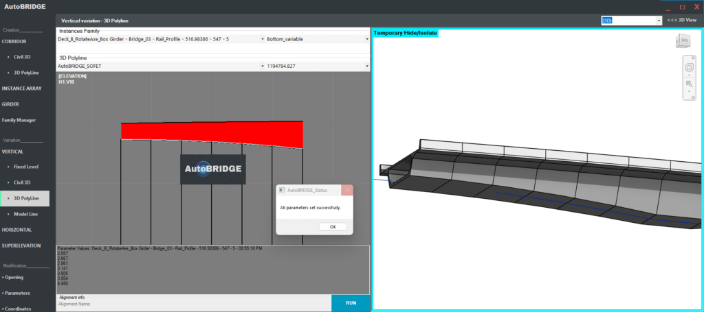
3D Polyline
This feature allows you to control the vertical variation parameter from a 3D polyline imported from AutoCAD.
- Select family name.
- Choose the parameter name.
- Select AutoCAD layer and polyline length.
- Add additional values if needed.
- Press Run to execute the process.
Refer to “Figure 17 – fixed level” for visual guidance.
Model Line
This feature allows you to control the vertical variation parameter Using vertical Model Line in Group:
- Select family name.
- Choose the parameter name.
- Select Model Line group name.
- Press Run to execute the process.
Refer to “Figure 19 – fixed level” for visual guidance.

Horizontal Variation
The Horizontal Variation feature provides precise control over an element’s shape in the horizontal plane, allowing you to adjust its edges using either model lines or imported 3D polylines. This flexibility ensures that even complex designs, such as road bifurcations, can be seamlessly managed.
3D Polyline
- Select family name.
- Select Left and Right 3D Polyline Layer, then Select Left and Right 3D Polyline length.
- Press Run to execute the process.
Refer to “Figure 20 – fixed level” for visual guidance.
Model Line
- Select family name.
- Select Left and Right Model lines groups.
- Press Run to execute the process.
Refer to “Figure 21 – fixed level” for visual guidance.


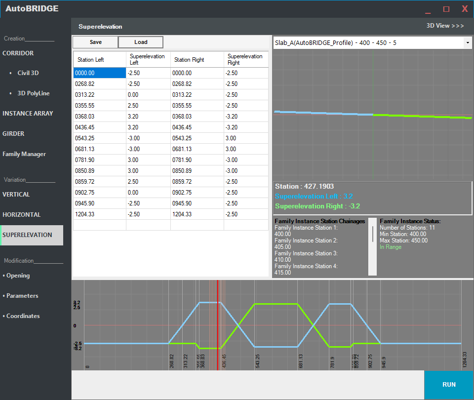
Superelevation
The Superelevation feature in AutoBRIDGE enables precise management and visualization of superelevation data for infrastructure elements. This interface allows users to configure and view left and right superelevation values across various stations.
Interface Overview
- Station Left & Right, Superelevation Left & Right: This table lists the stations with corresponding superelevation values, showing both left and right values. Scroll through to inspect or modify values for each station.
- Save and Load Buttons: Use the Save button to store the current superelevation data, and the Load button to retrieve previously saved configurations.
- Family Element Selection: The dropdown at the top right is used to select the family element you wish to work with.
- Graph View: This visualizes superelevation data across stations. The graph shows stations on the horizontal axis and superelevation values on the vertical axis, with lines indicating Left (blue) and Right (green) superelevation.
How to Use Superelevation
- Set Superelevation Values: Enter or modify values in the table under Station Left, Superelevation Left, Station Right, and Superelevation Right.
- Save Configuration: Click Save to store your current superelevation settings.
- Load Configuration: Use Load to retrieve and apply a previously saved superelevation configuration.
- Select Family Element: Use the dropdown to choose the specific family element. The graph and data will update to reflect the superelevation settings for the selected element.
- View Graph: The graph provides a visual representation of superelevation across stations, aiding in quick analysis and verification.
- Run Analysis: Click the Run button at the bottom right to apply and visualize the superelevation settings within your Corridor model.
(Refer to Figure 22)
Modification
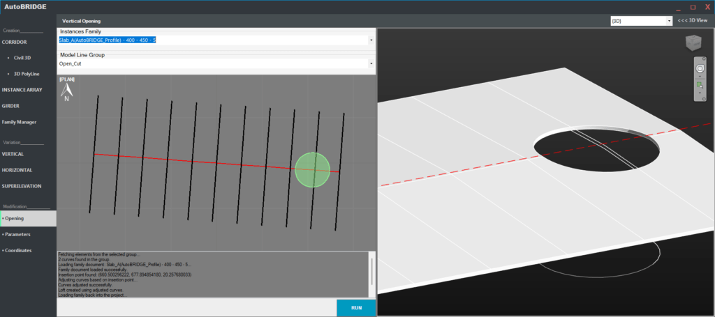
Vertical Opening
The Vertical Opening feature in AutoBRIDGE allows users to create customized vertical openings of any shape within selected family elements. This flexibility supports various design requirements, from circular holes to complex shapes, defined by model lines.
Interface Overview
- Instances Family: Choose the family instance you wish to modify from this dropdown. This selection defines the element where the vertical opening will be applied.
- Model Line Group: Select the model line group that outlines the shape and location of the opening. You can draw any shape using model lines, allowing for flexibility in defining unique opening geometries.
How to Use Vertical Opening
- Select Family Instance: Use the Instances Family dropdown to choose the family instance where the opening will be applied.
- Define Opening Shape with Model Lines: Use the Model Line Group dropdown to select the set of model lines that outline the shape and size of the opening. You can draw any shape needed for your design, whether it’s a circular, rectangular, or custom outline.
- Run the Operation: Click the Run button to apply the vertical opening to the selected family instance. AutoBRIDGE will process the shape, adjust curves if necessary, and cut the opening based on the model line outline.
(Refer to Figure 23)
Parameter Control
The Parameter Control feature in AutoBRIDGE provides a centralized interface for managing and assigning parameters to multiple elements, even if they belong to different families. This feature is designed to streamline parameter management by allowing users to apply consistent values to elements that share common parameters, regardless of family.
Interface Overview
- Element Selection Lists:
- The left panel displays a list of available elements.
- Use the arrow buttons (
>>to add,<<to remove) to move selected elements from the left panel to the right panel, indicating the elements you wish to control together.
- Parameter Table:
- The table below displays a list of common parameters shared by the selected elements.
- Each row represents a parameter, with the Parameter column listing the parameter name and the Value column allowing for input of the desired value.
- You can scroll through and edit the values as needed for each parameter.
How to Use Parameter Control
- Select Elements:
- In the left panel, locate and select the elements you want to apply common parameters to. These elements can belong to different families but must share the parameters you intend to modify.
- Use the
>>button to move the selected elements to the right panel for parameter control.
- Assign Parameter Values:
- In the Parameter Table, find the parameter you want to adjust and enter the desired value in the Value column.
- This change will apply to all selected elements in the right panel, ensuring consistent parameter values across different elements.
- Run the Operation:
- Once you have configured all required parameters, click the Run button to apply the changes. The parameter values will be assigned to each selected element, creating a consistent setup across multiple elements.
(Refer to Figure 24)
- Element Selection Lists:

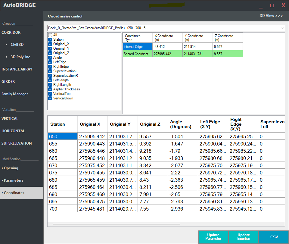
Coordinates Control
The Coordinates Control feature in AutoBRIDGE provides a comprehensive interface for managing and updating the coordinates of various elements. This feature allows users to export coordinates, update the insertion point and rotation if elements are moved, and synchronize coordinate parameters with the element’s new location.
Interface Overview
- Element List:
- The left panel displays a list of available coordinate parameters, such as
Original_X,Original_Y,Original_Z,Angle,LeftEdge,RightEdge, and superelevation parameters. Select the parameters you want to manage or export.
- The left panel displays a list of available coordinate parameters, such as
- Coordinate Types:
- This section at the top center shows key coordinate types like Internal Origin and Shared Coordinate, with their respective X, Y, and Z values.
- Coordinates Table:
- Displays detailed coordinate data, including
Station,Original X,Original Y,Original Z,Angle,Left Edge (X,Y),Right Edge (X,Y), and superelevation values. This table provides a comprehensive view of the spatial data for each station.
- Displays detailed coordinate data, including
- Action Buttons:
- Update Parameter: Synchronizes the coordinates in the table with the element’s current location, ensuring that parameter values reflect the element’s new position.
- Update Insertion: If the element has been accidentally moved, this option allows you to reset the element to its original saved location and rotation based on the stored parameters.
- CSV: Exports the selected coordinate data to a CSV file, including information such as station coordinates, angles, and edges.
How to Use Coordinates Control
Export Coordinates to CSV:
- Select the parameters you wish to include in the export from the left panel.
- Click the CSV button to export the data to a CSV file, which includes information such as station coordinates (X, Y, Z), angle, left and right edge coordinates, and superelevation values. This export is useful for documenting or analyzing spatial data outside of AutoBRIDGE.
Update Insertion Point and Rotation:
- If an element has been accidentally moved, click Update Insertion to reset its location and orientation based on the original parameters stored in the element. This action repositions the element to align with the saved coordinates, restoring the intended spatial configuration.
Update Coordinates Parameter Values:
- If an element has been moved intentionally and needs to retain its new position, select Update Parameter to adjust the coordinate parameter values to reflect the element’s new location. This update ensures that the stored parameters match the element’s actual placement within the model, allowing for accurate future reference.
(Refer to Figure 25)
- Element List:
Help
Troubleshooting
AutoBRIDGE is designed to be a user-friendly tool for infrastructure modeling within Autodesk Revit, but occasionally, issues may arise. Below are some common problems users encounter and suggested solutions to resolve them.
Installation Issues
Problem: The installer fails or displays an error during installation.
- Solution: Ensure that your system meets the minimum requirements for AutoBRIDGE and that you have the correct version of Autodesk Revit installed (e.g., Revit 2024 for AutoBRIDGE 2024).
- Solution: Disable any antivirus or security software temporarily, as these can sometimes interfere with the installation process.
- Solution: Run the installer as an Administrator by right-clicking the setup file and selecting “Run as administrator.”
Problem: AutoBRIDGE tab does not appear in Revit after installation.
- Solution: Restart Revit after the installation. If the tab still doesn’t appear, ensure that the AutoBRIDGE add-in files are correctly placed in the Revit add-ins folder. This folder is usually located in %ProgramData%\Autodesk\Revit\Addins\2024\.
- Solution: Verify the Revit version you’re using; AutoBRIDGE 2024 is only compatible with Revit 2024.
License Activation Issues
Problem: Unable to activate the AutoBRIDGE license.
- Solution: Ensure you are connected to the internet, as activation requires an online connection.
- Solution: Verify that the activation key was entered correctly. Ensure there are no extra spaces or characters.
- Solution: Contact AutoBRIDGE support if the issue persists, as it may be a problem with the activation server or your account.
Alignment Data Not Recognized from Civil 3D
Problem: AutoBRIDGE does not recognize alignment data from Civil 3D.
- Solution: Ensure Civil 3D is open and the correct document containing the alignment data is active before attempting to access it in AutoBRIDGE. AutoBRIDGE requires Civil 3D to be running with the intended alignment file open and active.
- Solution: Verify that the alignment is properly defined in Civil 3D and has a corresponding profile associated with it. Incomplete or incorrectly set up alignments or profiles can prevent AutoBRIDGE from accessing the data.
- Solution: Ensure that the Civil 3D version matches the one specified in the AutoBRIDGE About page. To verify, navigate to Help > About AutoBRIDGE Modeler on the first page of the AutoBRIDGE interface. This page displays the Civil 3D version that AutoBRIDGE is compatible with. Mismatched versions may lead to data recognition issues.
- Solution: Refresh the CIVIL 3D in AutoBRIDGE by closing and reopening the CIVIL 3D panel. If the alignment still doesn’t appear, restart both Civil 3D and Revit, then try again.
- Solution: If you’re working in a multi-user environment, ensure that other users are not actively modifying the alignment data in Civil 3D at the same time, as this could prevent AutoBRIDGE from reading the file.
- Solution: Check Civil 3D permissions if you’re accessing files on a network drive. Ensure that you have read and write access to the Civil 3D document. Restricted permissions can block data access.
Parameter Control Not Applying Consistently
Problem: Parameter values aren’t applying uniformly across selected elements.
- Solution: Confirm that all selected elements share the common parameters you intend to adjust. Elements from different families may not have identical parameter sets.
- Solution: Ensure that values are correctly entered in the Parameter Table and click “Run” to apply changes. If changes still don’t apply, try re-selecting the elements and re-entering the values.
Elements Move Unexpectedly After Using Coordinates Control
Problem: Elements shift unexpectedly after updating coordinates with the Update Parameter or Update Insertion options.
- Solution: Verify the coordinate data in the Coordinates Table before applying updates to ensure it matches the desired position.
- Solution: Use Update Insertion to reset the element back to its original stored position if it has moved unintentionally.
- Solution: If you need to keep the new position, make sure you select Update Parameter to synchronize the coordinate parameters with the current element location.
Superelevation Data Not Displaying Properly
Problem: Superelevation values are not displayed correctly in the table or graph.
- Solution: Ensure that superelevation data is inputted correctly in the grid and that left and right superelevation values are assigned as needed.
- Solution: If importing data from Civil 3D, make sure the file and alignment are compatible with AutoBRIDGE and that the superelevation profile data is complete.
- Solution: Reload the superelevation data by clicking the Load button to refresh the data visualization if changes aren’t appearing in the graph.
Model Lines or 3D Polylines Not Recognized for Corridor or Array Creation
Problem: AutoBRIDGE is unable to recognize model lines or 3D polylines during corridor or array creation.
- Solution: Check that the selected lines are on the correct layer in AutoCAD or Civil 3D, as specified in the AutoBRIDGE settings.
- Solution: Ensure the model lines or polylines are properly defined, continuous, and in the correct 3D alignment. Any gaps or discontinuities may cause errors.
- Solution: If the issue persists, try exporting the polylines from AutoCAD again, ensuring the correct units and alignment are maintained.
Vertical Opening Shape Not Displaying as Expected
Problem: The vertical opening does not match the shape defined by model lines.
- Solution: Double-check the model lines in the selected model line group to ensure they form a closed or continuous outline for complex shapes.
- Solution: Make sure the model line group selected in AutoBRIDGE corresponds to the intended opening shape. If adjustments are needed, edit the model lines and reapply the opening.
CSV Export Issues in Coordinates Control
Problem: Unable to export coordinate data to CSV or the CSV file appears incorrect.
- Solution: Verify that the correct parameters are selected in the left panel before clicking CSV.
- Solution: Ensure that AutoBRIDGE has write permissions in the destination folder where the CSV is being saved.
- Solution: If the data is incorrect or incomplete, try reloading the coordinates data and exporting again.
Performance Issues or Crashes
Problem: AutoBRIDGE performs slowly or crashes frequently during usage.
- Solution: Check that your system meets the minimum hardware requirements for both Revit and AutoBRIDGE. Upgrading memory (RAM) or graphics capabilities may help if your system is underpowered.
- Solution: Close other heavy applications to free up system resources while using AutoBRIDGE.
- Solution: If the issue persists, reinstall AutoBRIDGE or update to the latest version, as performance improvements may have been included in recent updates.
Corridor Creation Issues
Problem: Corridor creation fails or elements do not align with the Civil 3D alignment.
- Solution: Verify that the alignment and profile in Civil 3D are properly defined and match the parameters selected in AutoBRIDGE. If the profile is missing or incomplete, AutoBRIDGE may not be able to correctly interpret the data.
- Solution: Check that Civil 3D is active with the correct alignment document loaded. AutoBRIDGE requires the alignment file to be open and active in Civil 3D for accurate data reading.
- Solution: Ensure the Revit Nested Family selected in the Family Section of AutoBRIDGE is compatible with corridor creation. Certain families may lack necessary parameters or geometry for corridor alignment.
- Solution: If corridor elements are misaligned, adjust the chainages manually in the Chainages Section, ensuring they align with the intended distances along the alignment.
- Solution: Check if variation parameters (e.g., vertical, horizontal, superelevation) are set correctly. Incorrect settings can cause misalignment or prevent the corridor from displaying properly.
- Solution: Restart both Revit and Civil 3D, as complex alignment data can sometimes cause issues with data loading in AutoBRIDGE. Refreshing the software can clear temporary conflicts.
3D Polyline Import Issues
Problem: 3D Polyline data from AutoCAD is not recognized or doesn’t display correctly in Revit.
- Solution: Confirm that the AutoCAD layer associated with the 3D polyline is correctly selected in AutoBRIDGE. The polyline layer must be visible and active in AutoCAD for AutoBRIDGE to access it.
- Solution: Verify that the 3D polyline is continuous and does not have any breaks or gaps. Disconnected segments can cause AutoBRIDGE to misinterpret the polyline data.
- Solution: Ensure the polyline length matches the specified length in AutoBRIDGE. Inconsistent polyline length settings can cause scale or alignment issues.
- Solution: If importing from an older AutoCAD version, save the file in a compatible format (e.g., DWG 2018) to avoid compatibility issues with Revit and AutoBRIDGE.
- Solution: For complex polylines, try simplifying the geometry in AutoCAD by reducing unnecessary vertices. This can improve processing and prevent display issues in Revit.
Instance Array Issues
Problem: The instance array does not place elements accurately along the alignment.
- Solution: Check that the alignment and profile selected in AutoBRIDGE match those used in Civil 3D. Mismatched alignments or profiles can cause incorrect element placement.
- Solution: Confirm that the Revit family type chosen for the instance array is suitable for the alignment data. Each family type (e.g., Structural Column, Structural Framing) may have specific parameters that impact placement accuracy.
- Solution: If using 3D polyline data, ensure the polyline layer and length are correctly set. The polyline’s start and end points should align with the desired array locations.
- Solution: Review the rotation parameters in the Family Section of AutoBRIDGE. Incorrect rotation settings can cause elements to orient improperly.
- Solution: Verify the chainages entered in the Chainages Section. Ensure each chainage corresponds to the correct point along the alignment for accurate placement.
- Solution: Restart Revit and reopen the project if the array appears distorted or misaligned. Temporary software issues can occasionally disrupt accurate placement.
Family Manager Issues
Problem: Unable to save or reuse family templates in the Family Manager.
- Solution: Ensure that the nested family is fully defined and all required parameters are included before saving as a template. Missing parameters can prevent successful template creation.
- Solution: Check that the template storage location in AutoBRIDGE has write permissions. Without write access, templates may not save correctly.
- Solution: Restart AutoBRIDGE and Revit to refresh the Family Manager, as temporary memory issues can sometimes interfere with saving templates.
- Solution: If the template includes multiple nested families, verify that each nested family is compatible with the intended usage in AutoBRIDGE. Incompatible nested families can prevent successful template reuse.
Variation Parameters Control Issues
Problem: Variation parameters (vertical, horizontal, superelevation) are not applied as expected in corridor or instance array elements.
- Solution: Verify that variation parameters are enabled for the selected family. In some cases, families may lack the necessary parameters for vertical, horizontal, or superelevation adjustments.
- Solution: Ensure Civil 3D alignment or polyline data is accurately imported and matches the variation requirements. Incorrect alignment or profile data can prevent variation settings from applying correctly.
- Solution: Check if parameter names in AutoBRIDGE match those in Revit families. If parameter names are inconsistent, AutoBRIDGE may not apply variations correctly.
- Solution: If using superelevation, confirm that the superelevation data is correctly set up in Civil 3D or inputted manually in AutoBRIDGE. Incorrect superelevation values can affect the variation display.
- Solution: Restart Revit if the variation parameters appear distorted or incorrect, as this may resolve temporary rendering issues.
Chainages Input Issues
Problem: Chainages are not accurately recognized or applied within corridor or instance array elements.
- Solution: Verify that the chainages are entered in the correct units (e.g., meters) and correspond to the alignment distance. Mismatched units can cause placement errors.
- Solution: Ensure that chainage values match key points along the alignment. Chainages placed outside the alignment range may be ignored by AutoBRIDGE.
- Solution: If manually entering chainages, double-check values for accuracy. Minor typos or errors can disrupt the element placement.
- Solution: Use the “Lines” option to define chainages if the manual entry method is not producing the expected results. This allows chainages to be set based on model line intersections with the alignment.
General Performance Issues with Creation Features
Problem: Slow performance or lag when creating corridors, arrays, or importing polylines.
- Solution: Simplify alignment or polyline data in Civil 3D and AutoCAD by reducing unnecessary vertices or segments. Complex geometry can slow down processing.
- Solution: Close other applications to free up system resources, especially if working with large models or complex families.
- Solution: Increase RAM allocation or virtual memory in your system settings to improve performance with high-data tasks in AutoBRIDGE.
- Solution: If using multiple large families, consider modularizing your model by breaking it into smaller sections. This reduces load on AutoBRIDGE and improves responsiveness.
- Solution: Regularly save your project, as frequent AutoBRIDGE operations can occasionally cause temporary memory issues that affect performance.
Frequently Asked Questions (FAQ)
1. What is AutoBRIDGE, and how does it benefit infrastructure modeling?
- AutoBRIDGE is a powerful add-in for Autodesk Revit, specifically designed to streamline and automate the modeling of infrastructure elements, such as bridges, tunnels, retaining walls, and corridors. By integrating data from Civil 3D, AutoBRIDGE simplifies complex tasks like corridor creation, instance array generation, girder modeling, and parameter control, helping engineers and designers save time and maintain precision in their projects.
2. Which versions of Revit and Civil 3D are compatible with AutoBRIDGE?
- AutoBRIDGE 2024 is compatible with Revit 2024 and requires a compatible version of Civil 3D for integration with alignment data. Check the Help > About AutoBRIDGE Modeler section in the AutoBRIDGE interface to confirm the specific Civil 3D version required. Ensuring version compatibility is essential for full functionality.
3. How do I install AutoBRIDGE?
- To install AutoBRIDGE:
- Run the installer and follow the prompts.
- Accept the license agreement and confirm installation.
- Ensure the AutoBRIDGE add-in files are correctly placed in the Revit add-ins folder (usually located at
%ProgramData%\Autodesk\Revit\Addins\2024\). - After installation, restart Revit to load the AutoBRIDGE tab in the Revit toolbar.
4. Why isn’t the AutoBRIDGE tab appearing in Revit after installation?
- If the AutoBRIDGE tab doesn’t appear in Revit:
- Restart Revit to ensure the add-in loads.
- Check that the AutoBRIDGE files are in the correct add-ins folder.
- Confirm you’re using Revit 2024, as AutoBRIDGE 2024 is only compatible with this version.
5. How do I activate my AutoBRIDGE license?
- To activate AutoBRIDGE:
- Ensure you are connected to the internet.
- Enter the activation key exactly as provided.
- If activation fails, double-check the activation key for accuracy (no extra spaces or characters).
- If issues persist, contact AutoBRIDGE support.
6. Can I use AutoBRIDGE without Civil 3D?
- Yes, while many AutoBRIDGE features benefit from integration with Civil 3D data (such as alignment profiles for corridor and array creation), certain features, like manual parameter control, family management, and general Revit modeling tools, can be used without Civil 3D.
7. How do I update coordinates after moving an element in Revit?
- If you move an element in Revit and need to update its stored coordinates in AutoBRIDGE:
- Go to the Coordinates Control panel.
- Use Update Parameter to synchronize the coordinate parameters with the element’s new location.
- Alternatively, use Update Insertion to reset the element back to its original saved position if it was moved unintentionally.
8. What should I do if alignment data from Civil 3D is not recognized in AutoBRIDGE?
- If alignment data is not recognized:
- Ensure that Civil 3D is open with the correct document active.
- Check that the alignment and profile are fully defined in Civil 3D.
- Verify that the Civil 3D version matches the version required by AutoBRIDGE (see Help > About AutoBRIDGE Modeler for compatibility details).
- Try refreshing the Civil 3D panel in AutoBRIDGE or restarting both Revit and Civil 3D.
9. Can I apply parameter control to elements from different families?
- Yes, AutoBRIDGE allows you to apply parameter values to elements from different families, as long as they share common parameters. Use the Parameter Control feature to select and adjust parameters consistently across multiple elements.
10. How does the Superelevation feature work in AutoBRIDGE?
- The Superelevation feature allows you to manage and visualize superelevation data for road elements. You can input superelevation values manually or import them from Civil 3D. The graph displays left and right superelevation values across stations, helping you verify and adjust them accurately.
11. Can I export coordinate data from AutoBRIDGE?
- Yes, you can export coordinate data to a CSV file using the Coordinates Control panel. Select the parameters you want to include and click the CSV button. This is useful for documenting or analyzing spatial data outside of AutoBRIDGE.
12. How do I create an instance array using Civil 3D data?
- To create an instance array using Civil 3D data:
- Open the Instance Array panel.
- Select the Civil 3D document, alignment, and profile.
- Choose the Revit family type and define any necessary parameters (e.g., X, Y, rotation).
- Enter chainages to control element spacing along the alignment, then click Run to generate the instance array.
13. Why isn’t my corridor aligning with Civil 3D alignment data?
- If the corridor isn’t aligning correctly:
- Verify the alignment and profile in Civil 3D match the settings selected in AutoBRIDGE.
- Ensure chainages and variation parameters (vertical, horizontal, superelevation) are correctly set in AutoBRIDGE.
- Restart Revit and Civil 3D if misalignment persists, as temporary software issues can affect alignment.
14. Can I use model lines for creating corridors or arrays in AutoBRIDGE?
- Yes, AutoBRIDGE supports using model lines for creating corridors and instance arrays. You can select a model line group to define chainages based on intersections with the alignment. This option is useful if you prefer to work with Revit model lines over Civil 3D data.
15. How can I adjust an opening shape in AutoBRIDGE?
- To adjust a vertical opening shape:
- Go to the Vertical Opening panel.
- Select the family instance and model line group that defines the opening.
- Edit the model lines as needed to create the desired shape (e.g., circular, rectangular).
- Click Run to apply the updated shape to the opening.
16. How do I troubleshoot installation issues with AutoBRIDGE?
- If you encounter installation issues:
- Ensure your system meets the minimum requirements and that Revit 2024 is installed.
- Temporarily disable antivirus software, as it may interfere with installation.
- Run the installer as an Administrator.
- If the AutoBRIDGE tab doesn’t appear in Revit, check the add-ins folder for correct file placement.
17. Does AutoBRIDGE support custom templates for recurring projects?
- Yes, AutoBRIDGE’s Family Manager feature allows you to save and reuse custom templates, which helps streamline recurring projects by reducing repetitive work. You can add templates with predefined nested families for efficient and consistent project setup.
18. What should I do if AutoBRIDGE is slow or crashes frequently?
- If AutoBRIDGE performs slowly or crashes:
- Ensure your system meets the minimum hardware requirements for Revit and AutoBRIDGE.
- Close unnecessary applications to free up system resources.
- Consider upgrading memory (RAM) or graphics capabilities for better performance.
- Restart Revit and Reinstall AutoBRIDGE if issues persist.
19. Can I manually update coordinates in the Coordinates Control feature?
- Yes, you can manually update coordinates in the Coordinates Control panel. Enter the desired values in the Coordinates Table, then use Update Parameter to apply the changes to the element’s parameters, ensuring alignment with the new coordinates.
20. How do I access support if I encounter an issue not covered in the manual?
- If you experience issues not covered in the manual, visit our support page or contact our customer service team via email. Our support team is available to help you resolve technical issues and answer questions about AutoBRIDGE.
Best Practices for Using AutoBRIDGE
1. Ensure Compatibility Between Software Versions
- Use Compatible Versions: AutoBRIDGE is designed to work with specific versions of Autodesk Revit and Civil 3D. Ensure that you’re using the versions specified in the Help > About AutoBRIDGE Modeler section.
- Regularly Update Software: Keep AutoBRIDGE, Revit, and Civil 3D up-to-date. Updates may include performance improvements, bug fixes, and new features that enhance compatibility.
2. Set Up Civil 3D Files Carefully Before Importing
- Define Alignment and Profiles: In Civil 3D, define your alignment and associated profile completely before importing it into AutoBRIDGE. This ensures that AutoBRIDGE reads the correct data for corridor creation and instance arrays.
- Simplify Complex Polylines: Before importing 3D polylines from Civil 3D, simplify complex polylines by removing unnecessary vertices. This reduces processing time and prevents potential misalignment.
- Save Civil 3D Files in Compatible Formats: Save Civil 3D files in compatible formats (e.g., DWG 2018) to avoid import issues in Revit and AutoBRIDGE.
3. Organize Project Files and Folders
- Centralize Family Files: Store Revit family files used in AutoBRIDGE in a centralized folder structure. This makes it easier to reuse families across multiple projects and helps prevent file version issues.
- Use Logical Naming Conventions: Name alignments, profiles, families, and other project elements consistently to avoid confusion when selecting elements in AutoBRIDGE.
- Backup Regularly: Regularly back up your project files, especially if you’re working on large models or collaborating with other team members.
4. Optimize Parameter Control and Consistency
- Use Parameter Control for Multiple Families: When applying consistent parameters across multiple elements, use the Parameter Control feature in AutoBRIDGE. This ensures that shared parameters are applied uniformly, even across different families.
- Double-Check Parameter Names: Ensure that parameter names in AutoBRIDGE match those in Revit families. This helps avoid issues where parameters do not apply correctly due to mismatched names.
- Apply Changes in Batches: For efficiency, apply parameter changes in batches by selecting multiple elements at once in the Parameter Control panel. This can save time compared to modifying parameters individually.
5. Plan Chainages and Variation Parameters Carefully
- Define Chainages Strategically: Plan chainages in advance to optimize placement along the alignment. Accurate chainage planning can improve the placement of corridor and array elements along complex alignments.
- Use Variation Parameters When Necessary: If your design requires vertical, horizontal, or superelevation variations, configure these in AutoBRIDGE carefully. Adjust only the necessary parameters to avoid over-complicating the model.
- Use Lines for Chainages When Precise Control is Needed: If manual chainage entry doesn’t produce the desired results, use the Lines option to define chainages based on model line intersections with the alignment. This can provide greater accuracy.
6. Manage Superelevation Data Efficiently
- Input Superelevation Values Carefully: When inputting superelevation values, verify each value in the grid before applying them. Consistent data entry ensures a smoother workflow and prevents errors in the final model.
- Save and Load Configurations: Use the Save and Load buttons to store and retrieve superelevation configurations, especially if you work with similar superelevation profiles across projects. This helps maintain consistency and saves time on setup.
- Use Graph View to Verify Data: Before finalizing superelevation settings, check the Graph View to confirm the superelevation profile visually. This helps catch any discrepancies that may not be immediately obvious in the grid.
7. Leverage the Family Manager for Consistent Templates
- Create Reusable Templates: Use the Family Manager to save frequently used templates. This allows you to quickly apply standard configurations across projects, ensuring consistency and saving time on repetitive tasks.
- Include Nested Families for Complex Elements: For complex infrastructure elements, add nested families to the Family Manager. Nested families allow for more detailed configurations and are essential for creating accurate bridge and tunnel templates.
- Test Templates Before Applying: Test new templates on a sample project to verify that all parameters and nested families function as expected. This helps prevent issues when applying templates to live projects.
8. Use Coordinates Control for Accurate Placement
- Verify Coordinates Before Applying Updates: Before using Update Parameter or Update Insertion options, double-check coordinates in the Coordinates Table to ensure accurate placement.
- Export Coordinates for Documentation: Regularly export coordinate data to a CSV file for documentation and review. This can be useful for tracking placements and verifying consistency.
- Adjust Coordinates Incrementally for Precision: If making small adjustments, update coordinates incrementally to ensure elements align precisely with design requirements.
9. Maintain Performance by Managing Model Complexity
- Use Simplified Models Where Possible: For large projects, consider using simplified Revit families or proxy geometry for initial modeling. This reduces load on AutoBRIDGE and improves performance.
- Close Unnecessary Applications: Closing other heavy applications can free up system resources, improving AutoBRIDGE performance when working with large datasets or complex elements.
- Modularize Large Models: Divide large infrastructure projects into smaller, modular models that can be managed independently. This reduces memory usage and makes it easier to work with individual sections of the model.
10. Test Vertical Openings and Custom Shapes in Advance
- Create Test Openings: When creating vertical openings, especially custom shapes, test the opening on a sample model first to ensure the desired result.
- Ensure Model Lines Are Continuous: If using model lines to define a custom opening shape, verify that the lines form a continuous or closed outline. This prevents unexpected results and ensures the opening appears as intended.
- Save Model Line Groups for Reuse: Save frequently used model line groups that define specific shapes, such as circular or rectangular openings. This allows for quick reuse in future projects.
11. Regularly Review and Clean Up Model Data
- Delete Unused Elements: Regularly delete or purge unused families, templates, and alignments from your Revit model to keep it optimized and reduce file size.
- Check for Redundant Chainages or Parameters: Clean up any redundant chainages, parameters, or variations that are no longer needed. This keeps the model organized and reduces processing time.
- Regularly Save Project Versions: Save versions of your project regularly to maintain a history of changes. This is particularly useful when experimenting with AutoBRIDGE configurations and adjustments.
12. Use the Help Resources and Documentation
- Consult the User Manual: The AutoBRIDGE user manual contains step-by-step instructions for using each feature. Familiarize yourself with this resource to take full advantage of AutoBRIDGE’s capabilities.
- Watch Video Tutorials: For visual learners, video tutorials are available on the AutoBRIDGE website. These tutorials demonstrate key features and workflows, helping users understand complex tasks.
- Contact Support for Advanced Issues: If you encounter a complex issue that the documentation doesn’t cover, reach out to AutoBRIDGE support. The support team can help resolve technical issues and answer advanced questions.
13. Perform Final Checks Before Running AutoBRIDGE Operations
- Verify All Inputs: Before running operations in AutoBRIDGE (e.g., corridor creation, instance array generation), double-check all inputs, including alignment, family selection, chainages, and parameter values.
- Use Preview Features Where Available: Use preview features (such as Graph View for superelevation) to verify settings visually before applying them.
- Run in Incremental Steps for Large Models: For large models, run AutoBRIDGE operations in smaller steps to avoid overloading the system. Incremental processing can improve stability and prevent crashes.
Contact Information
If you encounter any issues or have questions about AutoBRIDGE, our support team is here to help. Below are the ways you can reach out for assistance, find resources, and connect with the AutoBRIDGE community.
1. Technical Support
For technical support, please contact our support team via email or visit our support page:
- Email: support@auto-bridge.net
- Support Page: https://www.auto-bridge.net
Our support team can assist you with installation, troubleshooting, and advanced usage questions. Please provide details about your issue, including any error messages and the steps leading up to the problem, to help us resolve it more efficiently.
2. Sales and Licensing Inquiries
For questions about purchasing, licensing, or subscription plans, please reach out to our sales team:
- Email: sales@auto-bridge.net
Our sales team can provide information on subscription plans, corporate licensing options, and custom requirements for larger teams. We offer flexible plans designed to meet the needs of individual users and organizations alike.
3. General Inquiries
If you have general questions about AutoBRIDGE, feedback, or suggestions for new features, we would love to hear from you! Contact us at:
- Email: info@auto-bridge.net
Your feedback helps us improve AutoBRIDGE and shape future updates. We’re committed to listening to our users and continuously enhancing our tools to meet the evolving demands of infrastructure design.
4. Community and Learning Resources
Stay connected and learn more about AutoBRIDGE through our online resources:
- Website: https://www.auto-bridge.net
- Video Tutorials: Our video tutorials are available on the AutoBRIDGE website, providing step-by-step demonstrations of key features.
- User Forum: Join our user forum on the website to connect with other AutoBRIDGE users, share tips, and find solutions to common challenges.
5. Social Media
Follow us on social media for the latest news, updates, and tips:
- LinkedIn: AutoBRIDGE LinkedIn Page
- Youtube: AutoBRIDGE Youtube Channel
By following us on social media, you can stay up to date with new releases, feature highlights, and helpful resources.
Thank you for choosing AutoBRIDGE to elevate your infrastructure modeling experience within Autodesk Revit. We are committed to providing innovative tools that simplify and streamline complex workflows, helping you achieve your design goals more efficiently.
AutoBRIDGE is more than just a software solution; it’s a growing community of engineers and designers dedicated to advancing infrastructure modeling. We encourage you to explore all the features, stay connected with our resources, and share your feedback. Together, we’re building the future of infrastructure design.
We’re here to support you at every step. Whether you’re working on a small project or a large-scale infrastructure model, AutoBRIDGE is designed to adapt to your needs and empower your creativity. Don’t hesitate to reach out if you have questions, and remember, we’re only an email away!
Happy modeling, and welcome to the AutoBRIDGE family!