
Corridor Creation via Civil 3D
Step-by-step guide to generating a fully parametric bridge corridor in Revit using a live Civil 3D alignment and profile as the geometry source. For the 3D PolyLine method, see the separate Corridor (3D PolyLine) manual.
What is Corridor Creation (Civil 3D)?
The Corridor Creation — Civil 3D workflow is one of two methods available in AutoBRIDGE for generating a bridge corridor. This method reads live geometric data directly from an open Civil 3D document — an alignment for horizontal path and a profile for vertical elevation — and generates a fully parametric 3D adaptive corridor family inside your Revit model.
If your project does not use Civil 3D, AutoBRIDGE also supports a 3D PolyLine source method — refer to the separate Corridor Creation (3D PolyLine) manual for that workflow.
The output of this workflow is a Generic Model adaptive family instance carrying the AutoBRIDGE_Type = "AutoBRIDGE_Corridor" parameter, which makes it immediately available as a source for all downstream AutoBRIDGE modules — Pier Designer, Girder Automation, and others.
Civil 3D Live Link
Reads alignment and profile directly from an open Civil 3D document — no manual data export or import required.
Nested Family System
Uses a nested adaptive family to define the cross-section shape. Solids and voids are mapped per subcategory for full flexibility.
Parametric & Updatable
The corridor auto-updates when Civil 3D geometry changes. Re-run at any time to synchronise your Revit model with the latest alignment data.
Prepare the Civil 3D Document
Before launching AutoBRIDGE, ensure your Civil 3D environment is correctly configured. The corridor workflow reads data live from the active Civil 3D session, so the document must be open and the alignment and profile must be finalised.
Open the Civil 3D File
Open the Civil 3D .dwg file containing the target alignment and its associated profile. Both must be fully defined — the alignment sets the horizontal path and the profile sets the vertical geometry that drives the corridor's elevation.
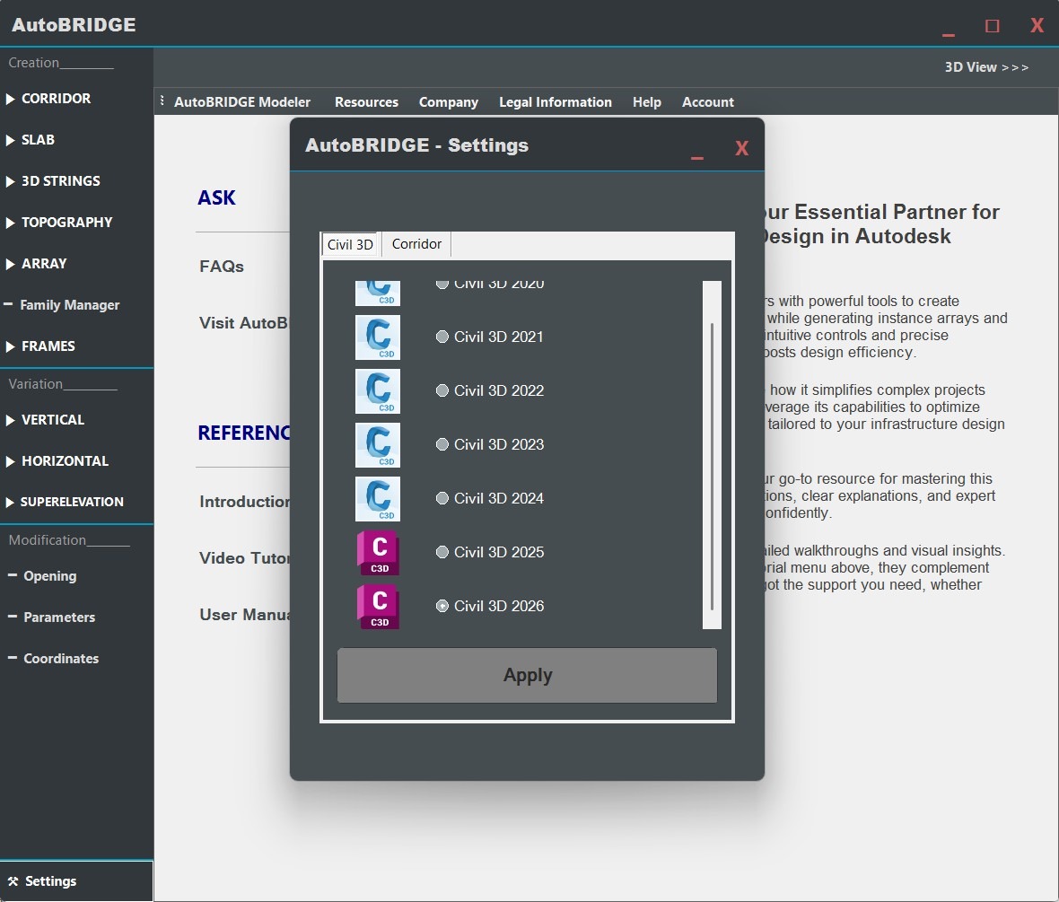
Version match: Confirm your Civil 3D version matches the setting in AutoBRIDGE under Settings → Civil 3D tab. If you change this setting after Revit is already open, a restart of Revit is required for the change to take effect.
Launch the Corridor Workflow
With Civil 3D open and your alignment ready, switch to Revit and open the AutoBRIDGE Corridor interface.
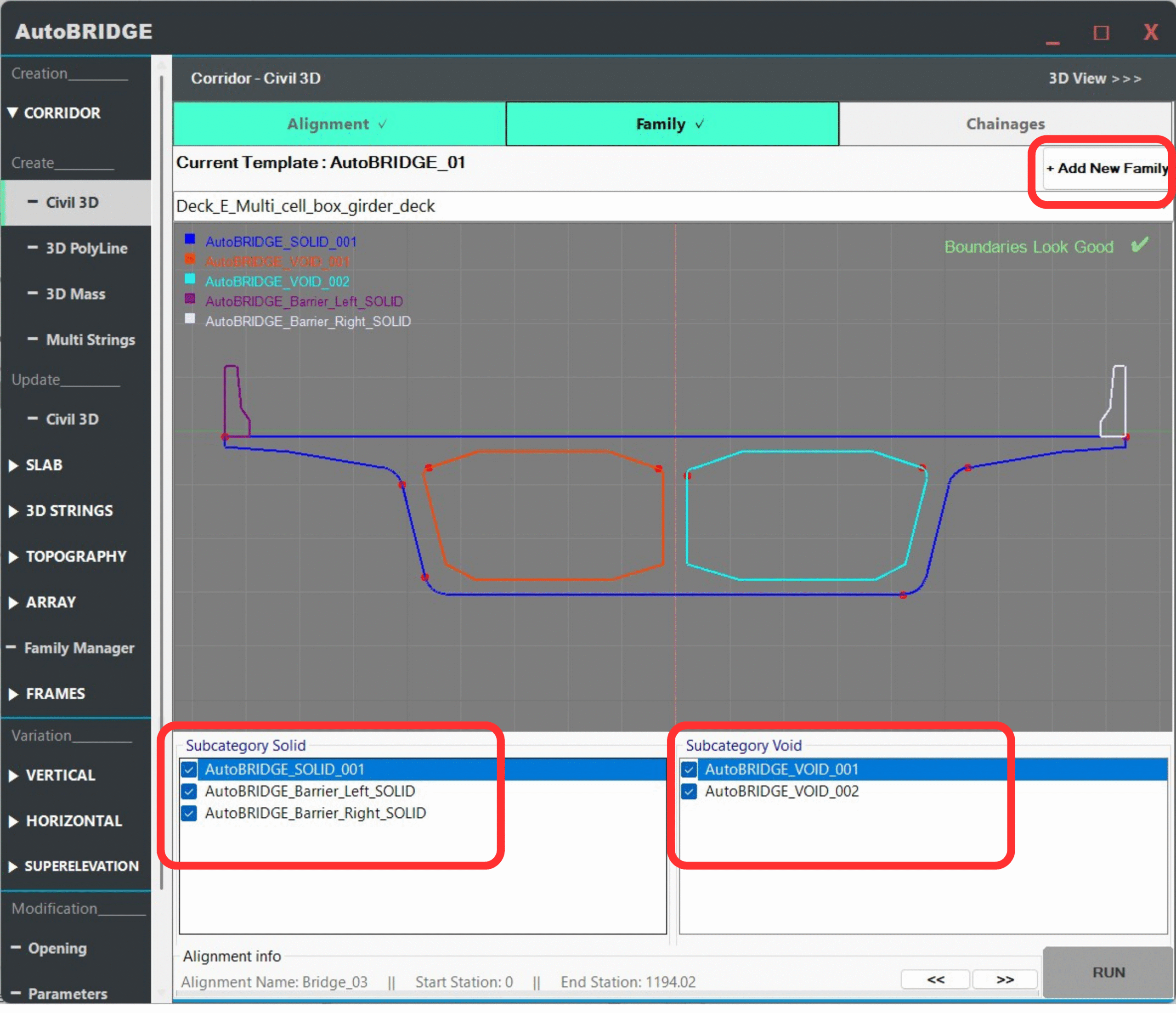
Open AutoBRIDGE → Corridor
In Revit, navigate to the AutoBRIDGE ribbon tab in the Add-Ins panel. Click the Corridor tool to launch the generation interface. The form opens as a borderless floating window with the blue cornflower border that identifies all AutoBRIDGE panels.
Select Alignment & Profile
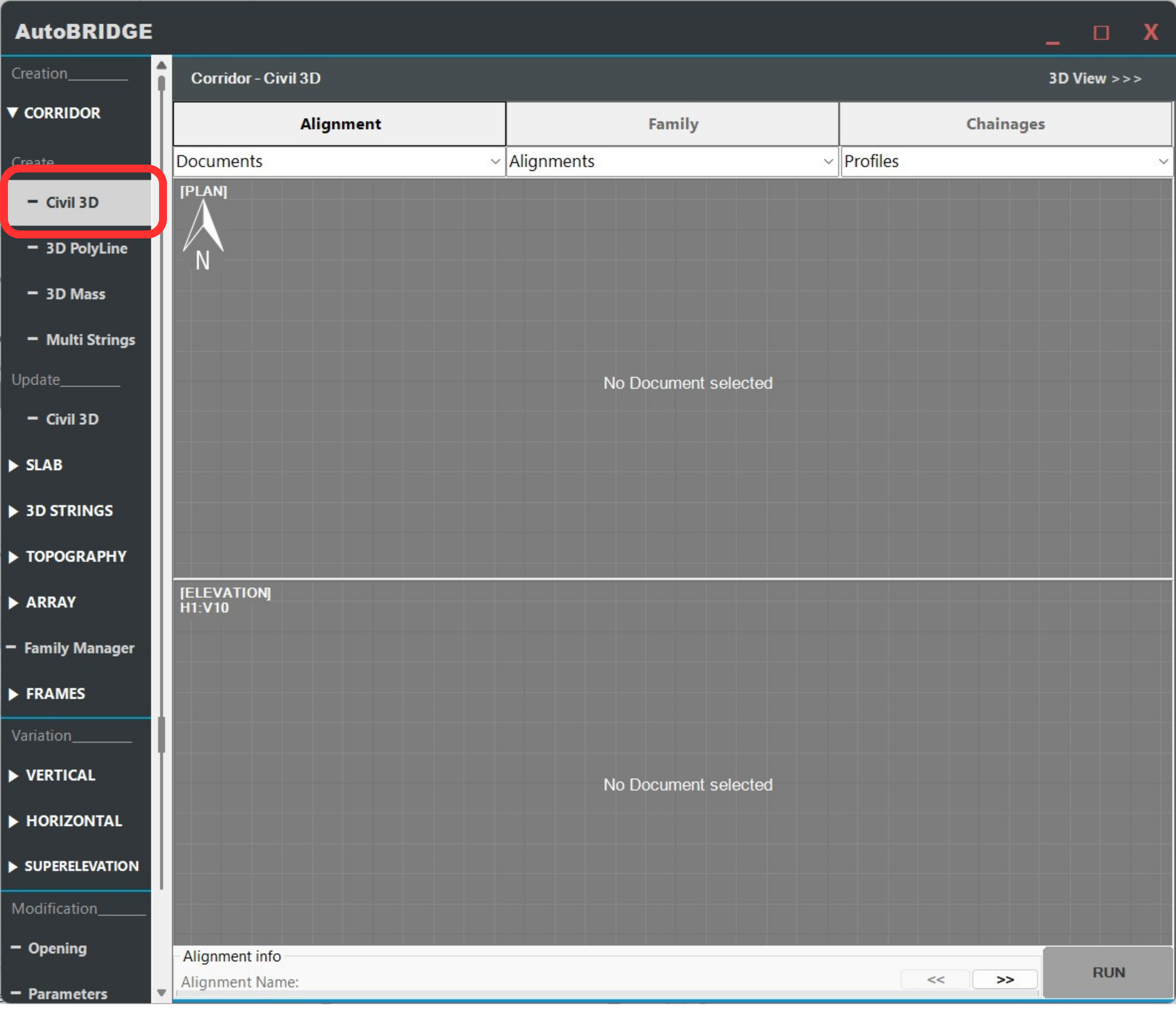
The first tab of the Corridor interface handles the data source. You select which Civil 3D document, alignment, and profile to use for corridor generation.
Choose Document, Alignment & Profile
From the Document dropdown, select your active Civil 3D session. AutoBRIDGE queries the live link to list all available alignments. Select the target Alignment, then choose the associated Profile from the next dropdown — this defines the vertical curve that the corridor will follow.
- Document — The open Civil 3D DWG session.
- Alignment — Horizontal path of the bridge centreline.
- Profile — Vertical geometry (elevation) along the alignment.
Family & Subcategory Configuration
The Family tab controls which cross-section shape is swept along the corridor path. AutoBRIDGE uses a nested adaptive family system — a host template wraps a nested family that defines the actual geometry.
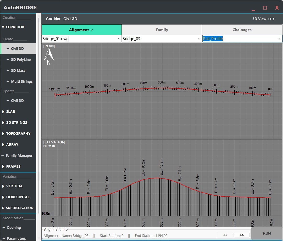
Assign Nested Family & Map Subcategories
Select a host Template family from the list, then choose or add your Nested Family — this is the adaptive cross-section shape that gets swept along the alignment. Once a nested family is loaded, map its geometry elements to the correct subcategories:
- Solid subcategory → structural and surface geometry visible in the model.
- Void subcategory → internal cuts, voids, or openings within the cross-section.
Proper subcategory mapping ensures that the generated corridor has correct visibility, material assignment, and scheduling behaviour in Revit.
Need a custom nested family for your corridor?
If you haven't created your adaptive nested family yet, follow the Family Manager & Adaptive Setup Workflow first. That guide walks through building a parametric cross-section from scratch and preparing it for use inside the Corridor tool.
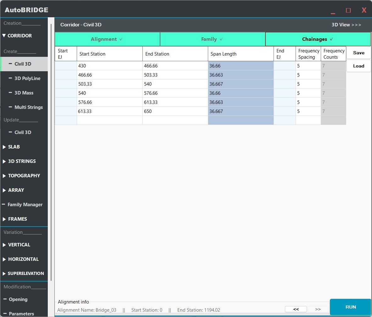
Define Chainages & Frequency
The Chainages tab is where you control the longitudinal extent of the corridor and how densely the adaptive sections are generated along it.
Input Stations & Set Frequency
Each row in the Chainages table represents an independently controlled corridor span. Set the Start and End station for each span in metres. The Frequency column defines the longitudinal spacing between adaptive cross-sections within that span.
- Start / End Station — Chainage along the Civil 3D alignment in metres. Multiple rows allow varying frequency or nested family types per segment.
- Frequency — Spacing in metres between generated adaptive family instances. Smaller values produce smoother curves but more elements.
Choosing the right frequency
| Frequency Value | Effect | Best Used For |
|---|---|---|
| Large (e.g. 5–10 m) | Fewer adaptive instances, faster generation, faceted curves | Straight or nearly-straight spans, preliminary design |
| Medium (e.g. 1–3 m) | Balanced detail and performance | Standard bridge spans with gentle curves |
| Small (e.g. 0.1–0.5 m) | Very smooth geometry, many instances, slower generation | Tight horizontal curves, detailed construction documentation |
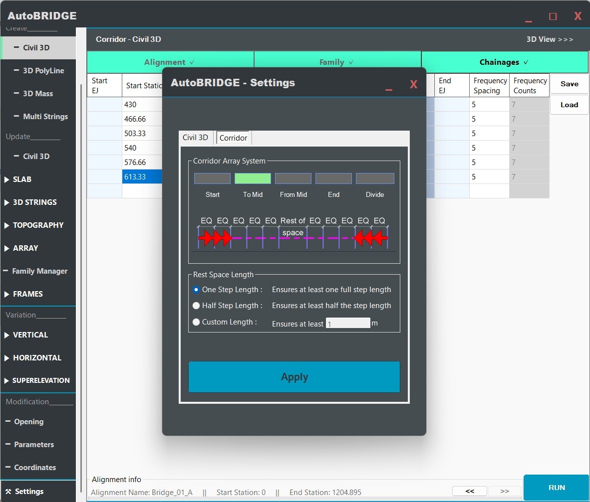
Generation Settings
Before running, the optional Settings → Corridor tab exposes additional controls over how family instances are arranged along each span.
Advanced Corridor Settings — Optional
Navigate to Settings → Corridor tab to access the Section Arrangement options. These control how AutoBRIDGE distributes the adaptive section instances across the span length:
- Start — Sections are anchored at the span start station and progress forward.
- End — Sections are anchored at the span end and progress backward.
- From Center — Distribution begins at the span midpoint and works outward symmetrically.
- To Center — Sections are distributed from both ends converging toward the midpoint.
For most bridge projects the default (Start) is appropriate. Use From Center when the span has a known midpoint expansion joint that must be respected.
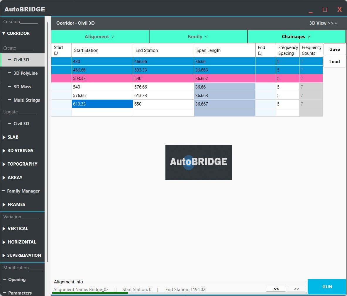
Run & Finalise
With alignment, family, chainages and settings confirmed, click the Run button to execute corridor generation. AutoBRIDGE connects to the live Civil 3D session, extracts the geometric data, and builds the corridor inside Revit.
Click Run — Process Corridor
The Run button triggers AutoBRIDGE to read the alignment XYZ data and profile elevations from Civil 3D at the specified station intervals. For each frequency step along each span, an adaptive cross-section family instance is placed in Revit at the correct position, bearing, and elevation. All instances carry the AutoBRIDGE_Type = "AutoBRIDGE_Corridor" parameter for downstream tool compatibility.
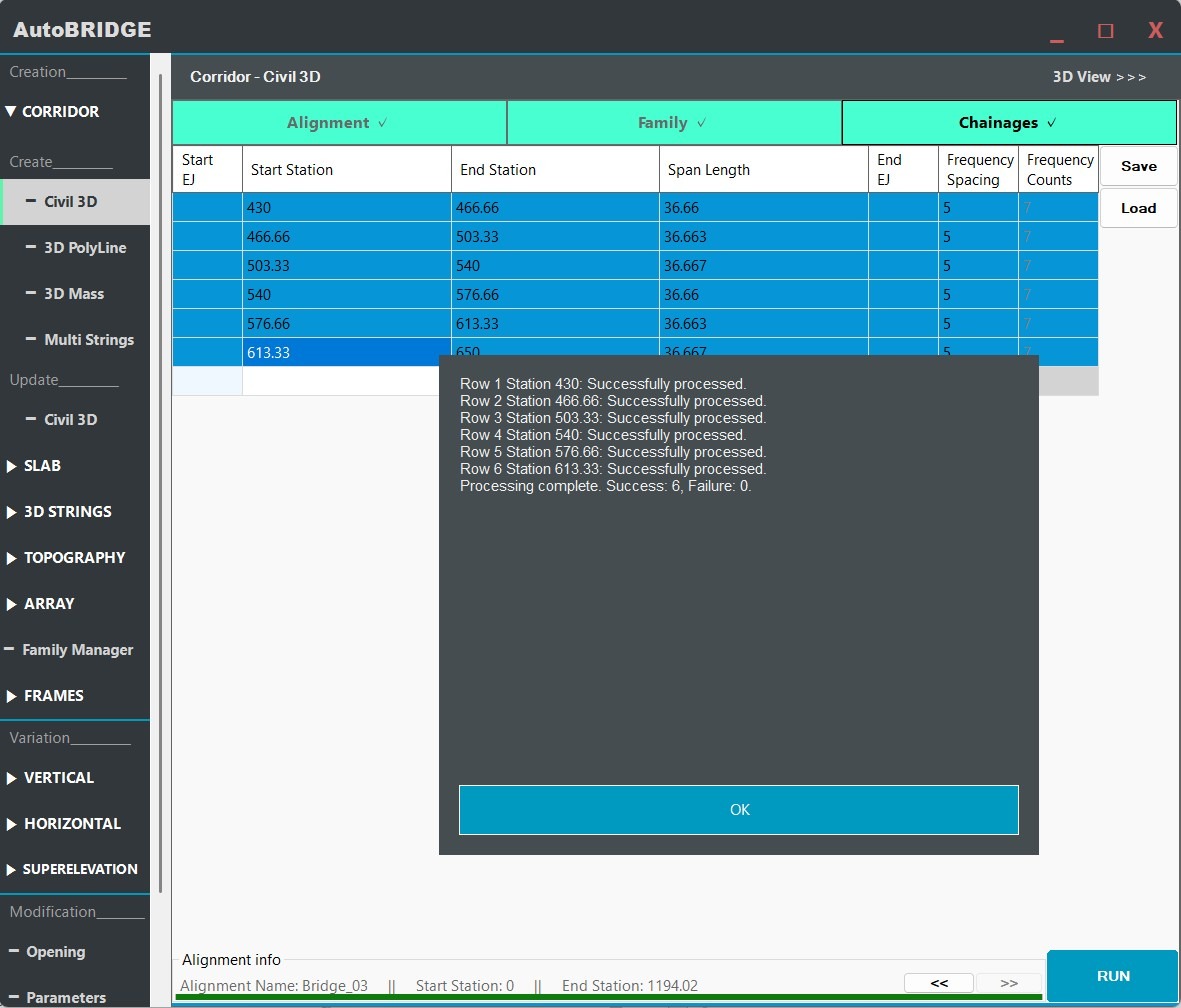
Success Confirmation & Result
Upon completion, a success dialog confirms the number of family instances created. Your corridor is now a fully parametric Revit model — each cross-section instance is driven by the Civil 3D geometry and can be updated by re-running the process at any time.
End-to-End Workflow
Open Civil 3D & verify the alignment and profile
Ensure the DWG is saved and the correct alignment + profile are active. Confirm Civil 3D version matches AutoBRIDGE settings.
Launch AutoBRIDGE → Corridor in Revit
Open the Corridor tool from the AutoBRIDGE ribbon tab. The interface appears as a floating panel.
Select Document, Alignment & Profile
Pick the live Civil 3D session and choose the alignment and profile that define the corridor path and elevation.
Assign the nested family & map subcategories
On the Family tab, select a template and nested adaptive family. Map geometry elements to Solid and Void subcategories.
Define chainages and frequency per span
Set start/end stations and frequency for each corridor span. Use smaller frequency values for smoother curved sections.
Check optional Settings (Section Arrangement)
Open Settings → Corridor for advanced placement options. The default Start arrangement suits most projects.
Click Run and verify the result
AutoBRIDGE generates all adaptive instances in a single Revit transaction. Confirm the 3D result and re-run if geometry quality needs improvement.
Troubleshooting
| Symptom | Likely Cause | Fix |
|---|---|---|
| Alignment / Profile dropdowns are empty | Civil 3D is not open or no named alignment exists | Open Civil 3D, load a DWG with at least one named alignment and profile, then re-open the Corridor form |
| Civil 3D version mismatch error | AutoBRIDGE is configured for a different Civil 3D version | Go to Settings → Civil 3D tab, update the version, then restart Revit |
| Corridor geometry looks faceted / angular | Frequency value is too large for the curvature of the alignment | Return to the Chainages tab and reduce the Frequency value for the affected span |
| Corridor does not appear in Pier Designer / Girder Automation | Family instance is missing the AutoBRIDGE_Type parameter |
Re-run the corridor generation — the parameter is assigned automatically during Run. Manually added families will not have this parameter. |
| Run completes but no instances appear in model | Start and End stations are outside the alignment extent, or the nested family failed to load | Check that station values fall within the alignment's chainage range; verify the nested family is correctly loaded and mapped |
| Corridor elevation is wrong | Wrong profile selected, or profile was not saved in Civil 3D before running | Save the Civil 3D file, confirm the correct profile is selected in the Profile dropdown, and re-run |
| Subcategory mapping produces missing geometry | Solid or Void subcategory not assigned to any family element | Return to the Family tab and ensure every visible element is assigned to the Solid subcategory |
Key Concepts
| Term | Description |
|---|---|
AutoBRIDGE_Type | Revit parameter automatically set to "AutoBRIDGE_Corridor" on every generated corridor family instance. Used by all downstream AutoBRIDGE tools to identify the corridor source. |
| Nested Family | An adaptive Revit family defining the bridge cross-section profile. Hosted inside the corridor template and swept along the Civil 3D alignment. |
| Frequency | Longitudinal spacing in metres between generated adaptive family instances. Smaller = smoother curves, more elements. |
| Span Row | One row in the Chainages table. Defines an independently controlled corridor segment with its own start, end and frequency settings. |
| Section Arrangement | Controls how adaptive instances are distributed within a span — Start, End, From Center, or To Center. |
| Solid / Void Subcategory | Family subcategory assignments that tell AutoBRIDGE which geometry is structural solid (visible) and which is a void (cut). |