
Corridor Creation via 3D PolyLine
Step-by-step guide to generating a fully parametric bridge corridor in Revit using a 3D PolyLine as the alignment source — no Civil 3D required. For the Civil 3D method, see the separate Corridor (Civil 3D) manual.
What is Corridor Creation (3D PolyLine)?
The Corridor Creation — 3D PolyLine workflow is the second method available in AutoBRIDGE for generating a parametric bridge corridor. Instead of a live Civil 3D link, this method uses a 3D PolyLine imported into Revit as the alignment source — making it ideal for projects that originate from survey data, third-party CAD software, or any workflow where Civil 3D is not in use.
The output is identical to the Civil 3D method: a Generic Model adaptive family instance tagged with AutoBRIDGE_Type = "AutoBRIDGE_Corridor", fully compatible with Pier Designer, Girder Automation, and all other downstream AutoBRIDGE tools.
No Civil 3D Needed
Works directly with any 3D PolyLine from a linked DWG, imported CAD file, or natively drawn Revit detail line with Z values.
Layer-Based Selection
Polylines are selected by their CAD layer name, then by their length — giving precise control when multiple polylines share a layer.
Lines Option for Spans
Draw a group of transverse cross-lines over the polyline in Revit and AutoBRIDGE auto-generates all span start/end stations from the intersections.
Insert the 3D PolyLine
The first step is to get the 3D PolyLine into your Revit project so AutoBRIDGE can read it. The polyline carries all the horizontal and vertical geometry — it replaces both the alignment and the profile that the Civil 3D method uses.
Insert the PolyLine Alignment into Revit
Link or import your DWG file containing the 3D PolyLine into the Revit project. The polyline must be a true 3D PolyLine — its vertices must carry Z elevation values that represent the finished bridge profile. A flat 2D polyline will produce a corridor with no vertical curvature.
Once inserted, navigate to AutoBRIDGE → Corridor → 3D PolyLine from the ribbon to launch the interface.
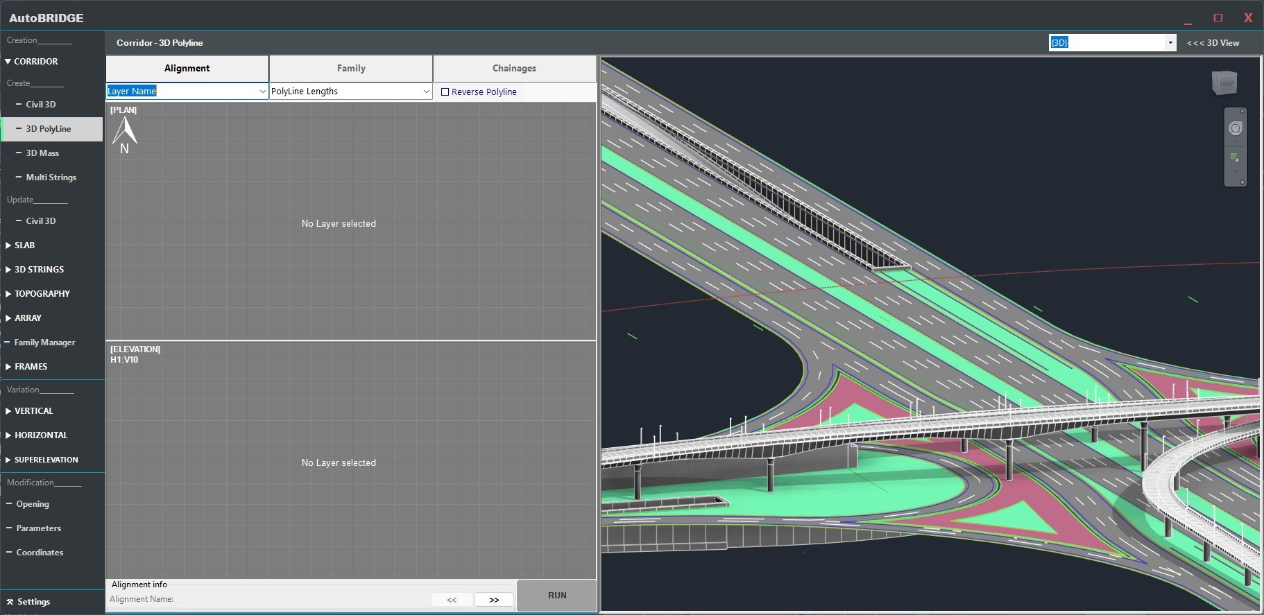
Select the PolyLine
The Alignment tab is where you identify which polyline from the CAD data will drive the corridor geometry.
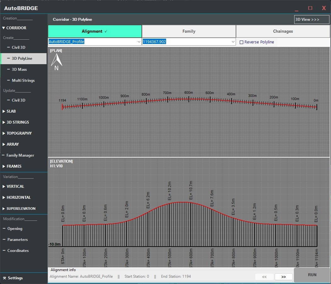
Choose Layer & Identify the PolyLine
In the Alignment tab, open the layer dropdown and select the CAD layer that contains your 3D PolyLine. AutoBRIDGE scans the linked file and lists all polylines found on that layer. Identify the correct polyline by its total length — each entry in the list shows the polyline's measured length, which is the most reliable way to distinguish between multiple polylines on the same layer.
- Layer name — must match the layer the 3D PolyLine is drawn on in the DWG.
- Length identifier — select the polyline whose length matches your bridge centreline length.
Family & Subcategory Setup
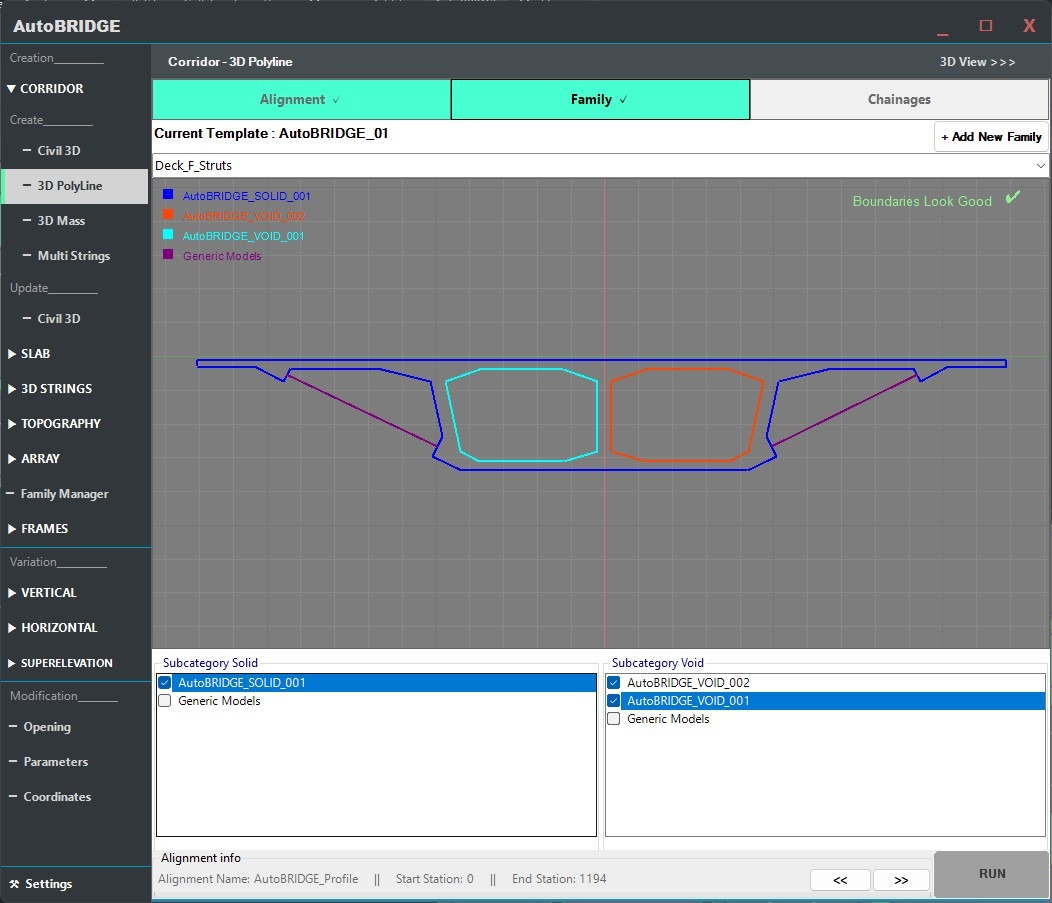
The Family tab is identical to the Civil 3D method. It controls which adaptive cross-section shape is swept along the polyline path.
Assign Nested Family & Map Subcategories
Select a host Template family, then choose your Nested Family — the adaptive cross-section that gets swept along the 3D PolyLine. Map its geometry elements to the correct subcategories:
- Solid subcategory → structural and surface geometry visible in the Revit model.
- Void subcategory → internal cuts or openings within the cross-section.
Correct subcategory mapping ensures proper visibility, material assignment, and schedule behaviour in Revit views.
Need a custom nested family for your corridor?
If you haven't created your adaptive nested family yet, follow the Family Manager & Adaptive Setup Workflow first. That guide walks through building a parametric cross-section from scratch and preparing it for use in the Corridor tool.
Define Chainages & Frequency
The Chainages tab controls the longitudinal extent of each corridor span and the density of adaptive cross-sections along it. This tab works exactly as in the Civil 3D method — with the addition of the Lines option for automatic span generation.
Manual Entry — Start & End Stations with Frequency
Each row in the Chainages table represents one corridor span with independent settings. Enter the Start and End station in metres for each span, and set the Frequency — the longitudinal spacing between generated adaptive cross-sections within that span.
- Start / End — chainage in metres measured along the 3D PolyLine from its starting vertex.
- Frequency — spacing in metres between adaptive instances. Smaller values produce smoother curves.
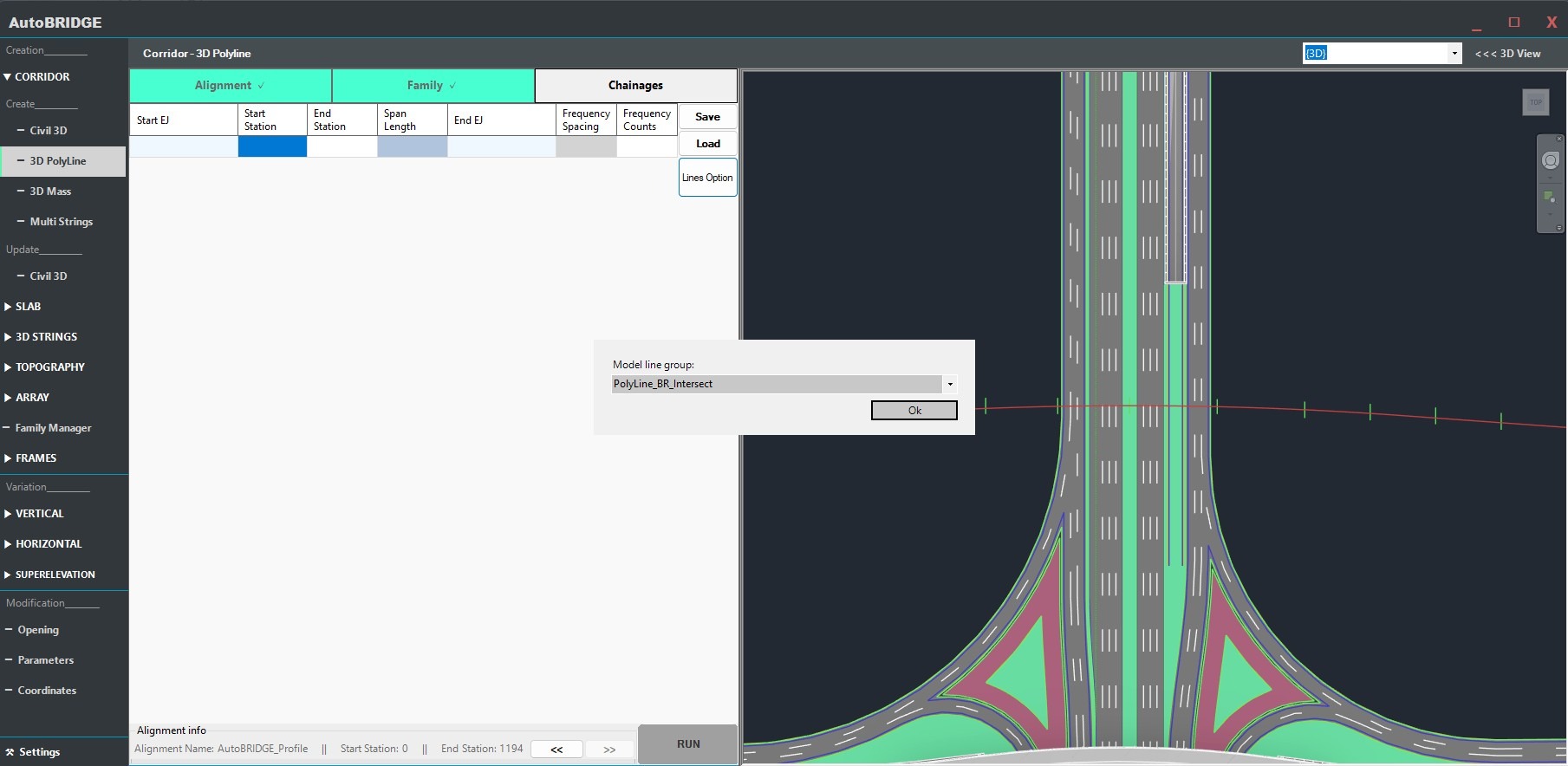
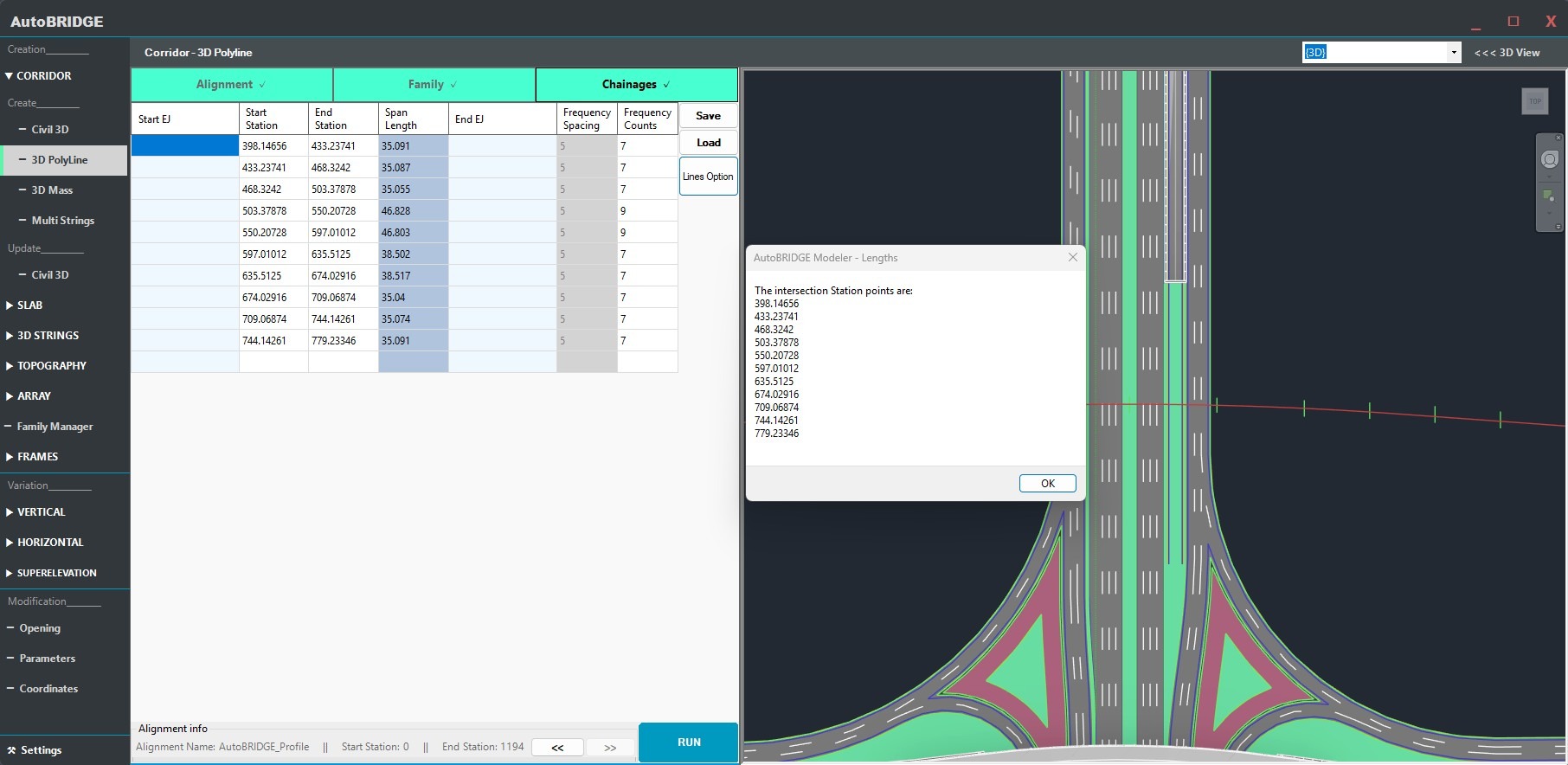
Lines Option — Auto-Generate Span Stations
For bridges with many spans or complex span arrangements, the Lines option automates station entry. In Revit, draw a set of transverse lines crossing the polyline alignment at each span boundary — these represent pier lines, abutments, or any structural reference. Group all the lines together using Create Group, give the group a name, then back in the Chainages tab:
- Select the Lines option in the tab.
- Choose the group name from the dropdown.
- Press OK — AutoBRIDGE intersects each group line with the polyline path and automatically populates the Chainages table with a row for every span.
This is the fastest way to set up chainages when pier positions are already drawn as reference lines in the Revit model.
Choosing the Right Frequency
| Frequency Value | Effect | Best Used For |
|---|---|---|
| Large (5–10 m) | Fewer instances, faster generation, faceted on curves | Straight spans, preliminary design stage |
| Medium (1–3 m) | Balanced detail and performance | Standard spans with gentle curvature |
| Small (0.1–0.5 m) | Very smooth geometry, high instance count, slower generation | Tight horizontal curves, final documentation |
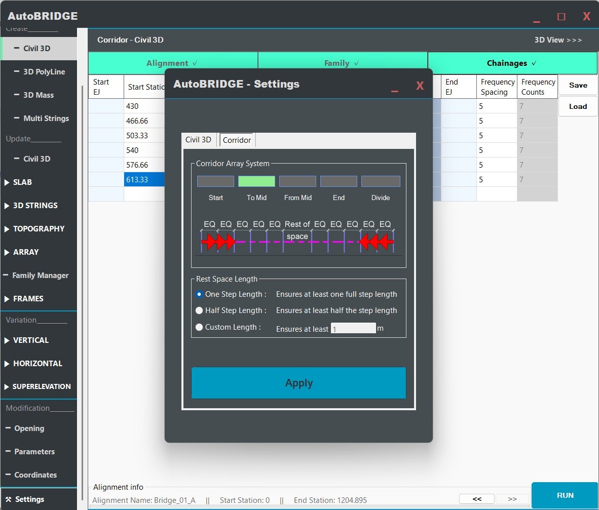
Optional Advanced Settings
Before running, the Settings → Corridor tab provides additional control over how adaptive instances are distributed within each span. These settings are identical across both corridor creation methods.
Section Arrangement — Optional Fine-Tuning
The Section Arrangement option controls where AutoBRIDGE anchors the adaptive instance distribution within a span. Choose the mode that best suits your project requirements:
- Start — instances begin at the span start station and progress forward. Suitable for most standard bridge spans.
- End — instances begin at the span end and progress backward.
- From Center — distribution starts at the span midpoint and works symmetrically outward. Ideal when a mid-span expansion joint must be honoured.
- To Center — instances converge from both ends toward the midpoint.
For typical workflows, leave this at the default Start setting and proceed to Run.
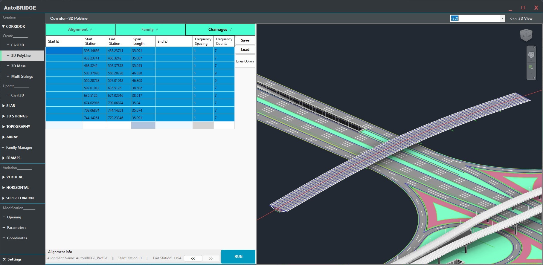
Run & Finalise
With the polyline selected, family mapped, chainages defined and settings confirmed, click Run to generate the corridor. AutoBRIDGE reads the 3D PolyLine vertex data, calculates positions at each frequency step, and places the adaptive cross-section instances in Revit.
Click Run — Generate the Corridor
The Run button processes all span rows in sequence. For each frequency step along each span, an adaptive family instance is placed at the correct 3D position and bearing derived from the polyline geometry. Each instance is tagged with AutoBRIDGE_Type = "AutoBRIDGE_Corridor" automatically.
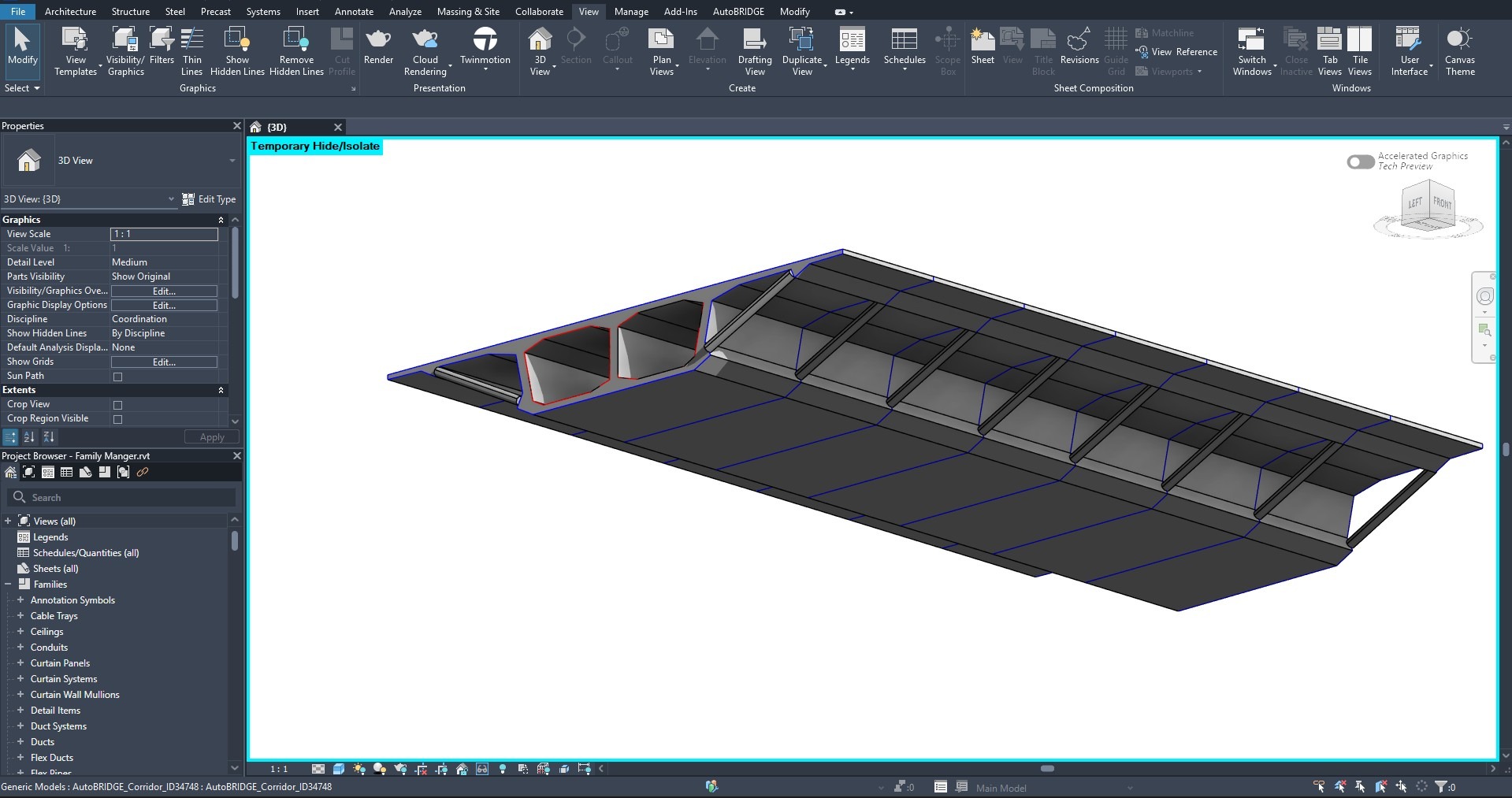
Success Confirmation & Result
A success dialog confirms how many adaptive instances were placed. Your corridor is now a fully parametric Revit model driven by the 3D PolyLine geometry — ready to use as the alignment source for Pier Designer, Girder Automation, and other AutoBRIDGE modules.
End-to-End Workflow
Link the DWG containing the 3D PolyLine into Revit
Use Link CAD (not Import) so the file can be refreshed later. Confirm polyline vertices carry Z elevation data.
Open AutoBRIDGE → Corridor → 3D PolyLine
Launch the interface from the AutoBRIDGE ribbon tab. On the Alignment tab, select the CAD layer and identify the polyline by length.
Assign the nested family and map subcategories
On the Family tab, choose a template and nested adaptive family. Map geometry to Solid and Void subcategories.
Define span chainages and frequency
Enter start/end stations manually per span, or use the Lines option to auto-generate spans from transverse reference lines drawn in Revit.
Check optional Settings (Section Arrangement)
Open Settings → Corridor for advanced placement options. Default Start arrangement suits most projects.
Click Run and verify the result
AutoBRIDGE generates all adaptive instances from the polyline data. Confirm geometry in 3D view and reduce frequency if curves appear faceted.
Civil 3D vs 3D PolyLine — Method Comparison
| Feature | Civil 3D Method | 3D PolyLine Method |
|---|---|---|
| Software required | Civil 3D must be open alongside Revit | Revit only — no Civil 3D needed |
| Alignment source | Named Civil 3D Alignment + Profile | 3D PolyLine in a linked DWG |
| Vertical geometry | Separate Civil 3D Profile (design or existing) | Embedded in the polyline Z values |
| Live update | Re-run syncs with latest Civil 3D data | Re-link DWG, then re-run to update |
| Span definition | Manual station entry in Chainages tab | Manual entry or Lines option (auto-intersect) |
| Output corridor | AutoBRIDGE_Type = "AutoBRIDGE_Corridor" | AutoBRIDGE_Type = "AutoBRIDGE_Corridor" |
| Downstream compatibility | All AutoBRIDGE modules | All AutoBRIDGE modules |
Troubleshooting
| Symptom | Likely Cause | Fix |
|---|---|---|
| Layer dropdown is empty | No CAD file is linked in the Revit project | Use Insert → Link CAD to link the DWG, then re-open the Corridor form |
| Polyline list is empty after selecting a layer | The selected layer contains no 3D PolyLines, or the elements are 2D | Confirm the DWG layer contains true 3D PolyLines (not 2D Polylines or splines) |
| Corridor elevation is flat or at Z = 0 | Polyline vertices have no Z values — it is a 2D polyline | Edit the DWG in CAD, ensure all vertices have correct Z elevations, re-link and re-run |
| Corridor appears faceted / angular | Frequency is too large for the curve radius | Return to Chainages tab and reduce the Frequency value for the affected span |
| Lines option produces no span rows | Group lines do not intersect the polyline within Revit's tolerance | Ensure the group lines physically cross the polyline alignment in plan; check that the correct group name is selected |
| Corridor not visible in Pier Designer / Girder Automation | Family instance missing AutoBRIDGE_Type parameter |
Re-run the corridor generation — the parameter is set automatically. Manually placed families will not have this parameter. |
| Run completes but no instances appear | Station values fall outside the polyline's measured length | Check that Start and End values are within the total polyline length shown in the Alignment tab |