Add Custom Nested Family for Corridor
Build a parametric adaptive cross-section family from scratch, configure subcategories, and deploy it through AutoBRIDGE Family Manager to generate a fully controlled bridge corridor.
Why Build a Custom Nested Family?
AutoBRIDGE generates corridors by sweeping a nested adaptive family along an alignment. The nested family defines the bridge cross-section shape — deck slab, girders, voids, barriers. Building a custom one gives you complete control over the geometry, parameters, and subcategory assignments used across the entire corridor.
Adaptive Points
Drive section rotation and superelevation from a single parameter.
Parametric Dims
Instance parameters control width, depth, and asphalt thickness.
Subcategories
Solid and Void subcategories mapped to correct geometry elements.
Reusable
Templates save across projects — build once, deploy on any corridor.
Validated
AutoBRIDGE confirms family is correctly detected before corridor run.
- All parameters must be set to Instance (not Type).
- All parameters must be formula-free — the formula column must remain empty for every parameter.
Family Manager Interface
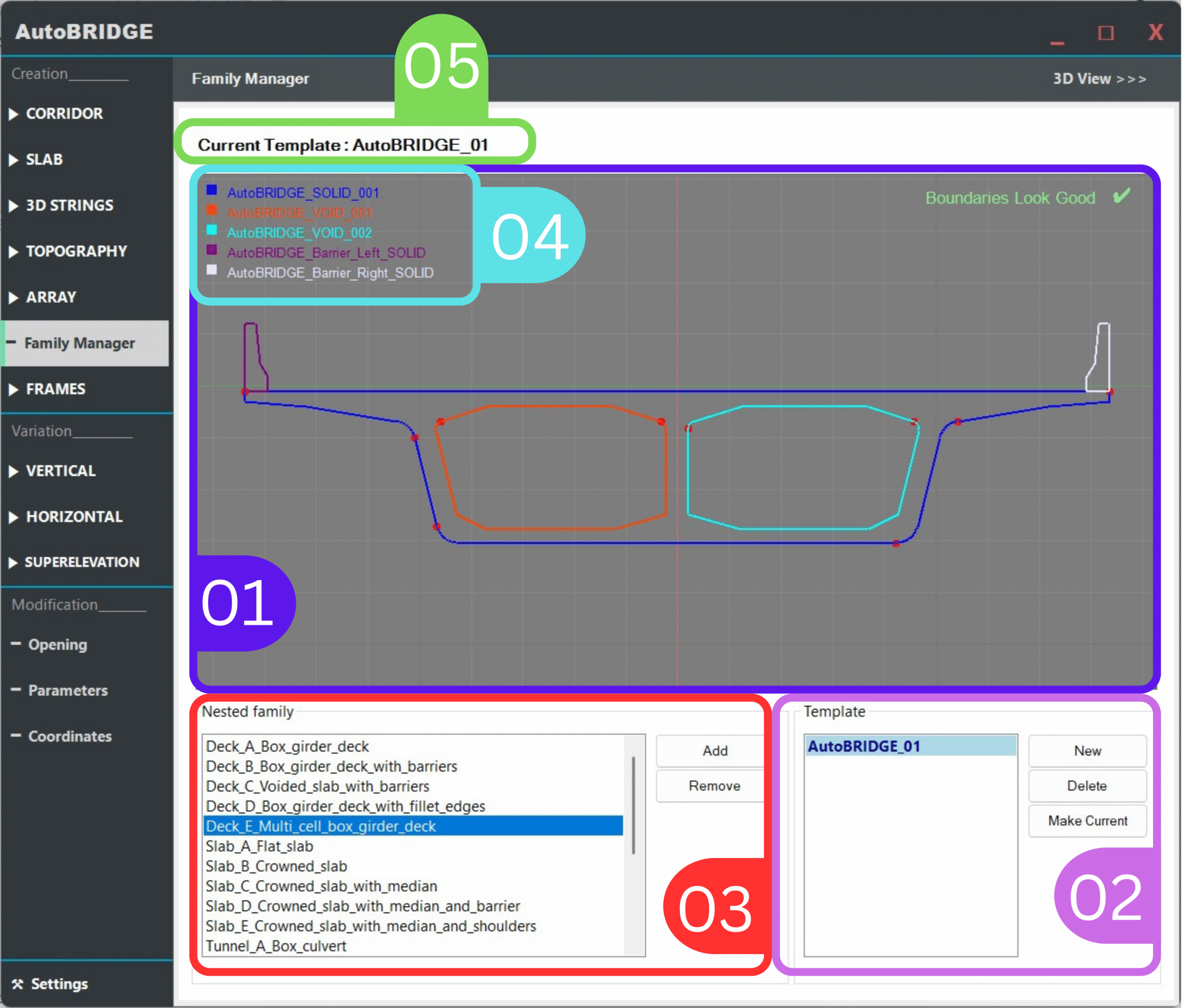
Before diving into the build steps, it helps to understand the five zones of the Family Manager panel you will use in Phase 4:
| # | Zone | Purpose |
|---|---|---|
| 1 | Nested Family Preview | Live 2D cross-section preview of the currently selected nested family, colour-coded by subcategory. |
| 2 | Template Section | Create, rename, and switch between templates. Each template holds a set of nested families for a project or family of bridges. |
| 3 | Nested Family List | Lists all nested families registered within the active template. Add and remove families here. |
| 4 | Subcategory List | Shows the solid and void subcategories detected inside the selected nested family. |
| 5 | Current Template | Indicates which template is active and will be used when creating a corridor. |
Adaptive Family Creation
Start by creating a new Metric Generic Model Adaptive family. This is the cross-section container that AutoBRIDGE will sweep along the alignment. Alternatively, copy the existing template from the AutoBRIDGE install folder and modify it — much faster for most projects.
nested_family_template from below, then update its geometry. This ensures all required parameters are already present.
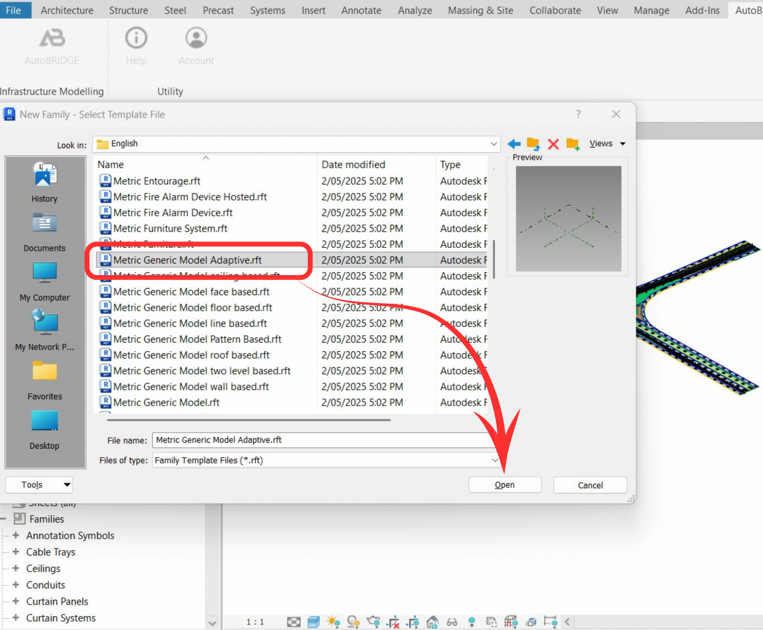
Create a Metric Generic Model Adaptive Family
Go to File → New → Family and select the Metric Generic Model Adaptive template. Open the new family editor.
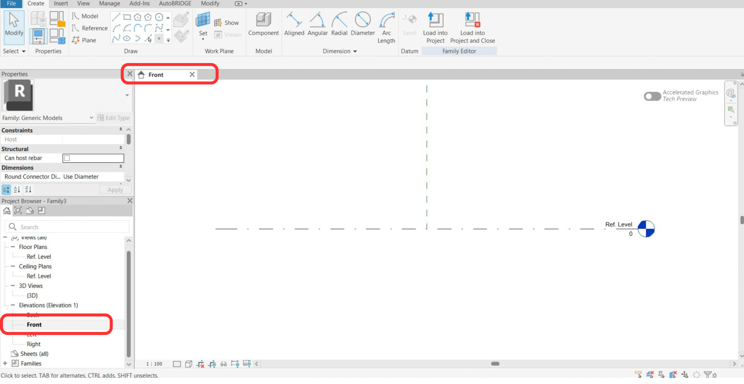
Open Front View
Switch to the Front view in the Project Browser. This is where the cross-section geometry and adaptive point will be built.
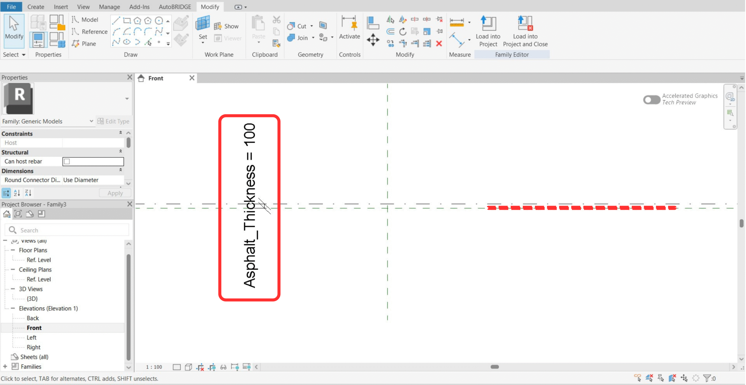
Add Asphalt Reference Plane & Parameter
Draw a reference plane at the asphalt depth offset and assign a dimension parameter (e.g. Asphalt_Thickness) to control it. This lets the asphalt layer thickness be varied per corridor span.
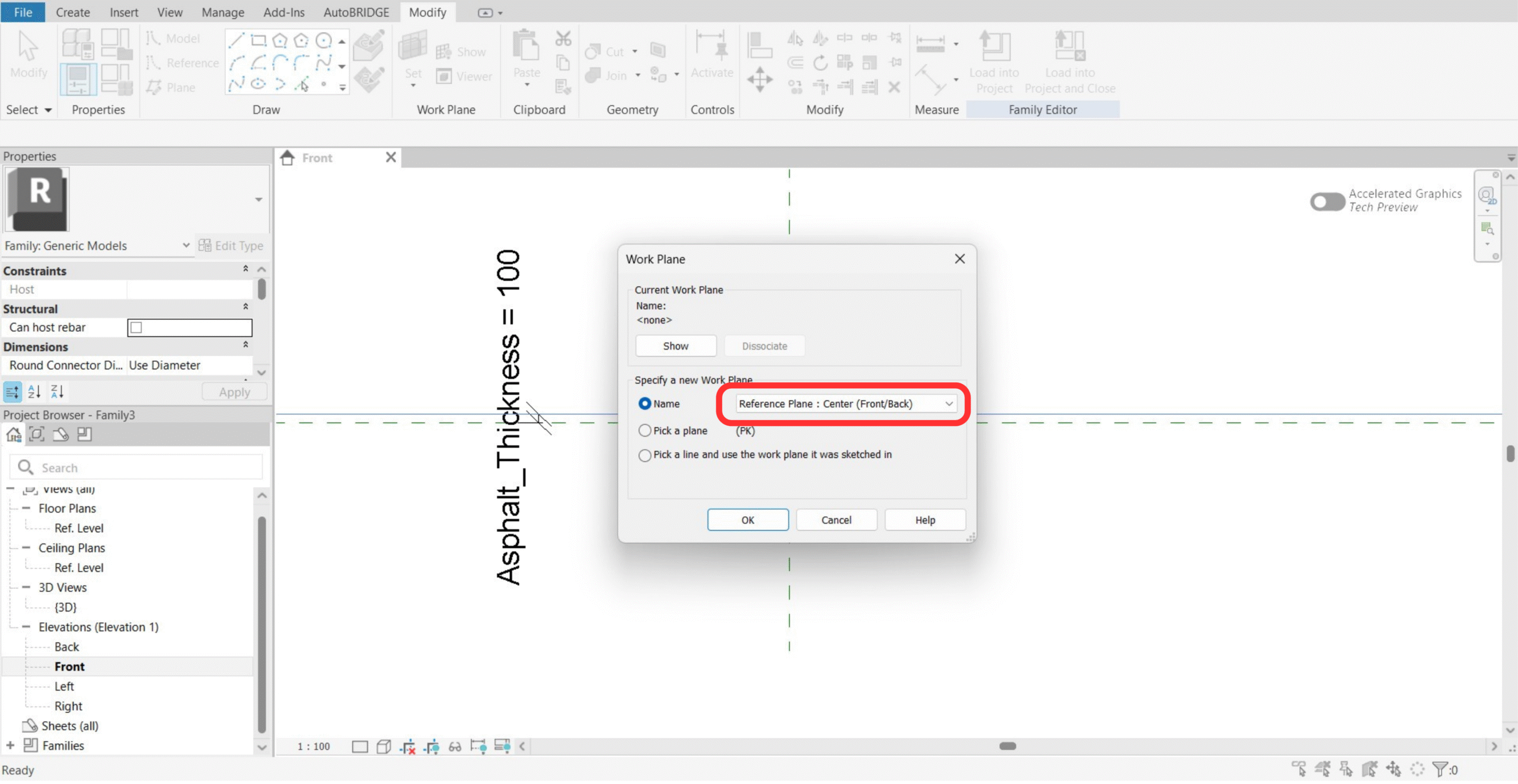
Set Work Plane to Center (Front)
Before placing the adaptive point, go to Set Work Plane and pick Center (Front). This ensures the adaptive point is placed at the correct origin for rotation control.
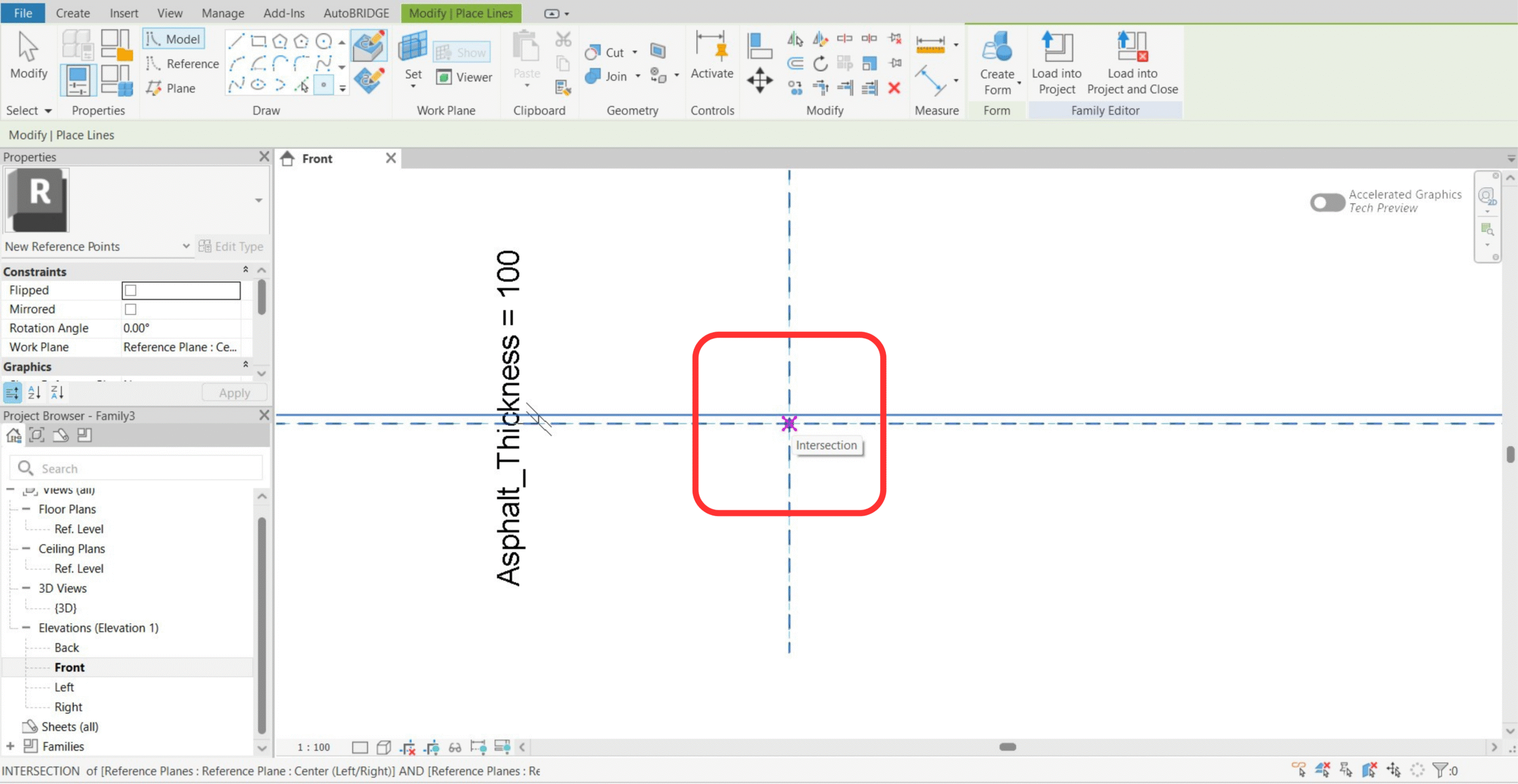
Add the Intersection Adaptive Point
Place an adaptive point at the intersection of the vertical Center (Front) reference plane and a new horizontal reference plane. This intersection point is the rotation pivot for the cross-section.
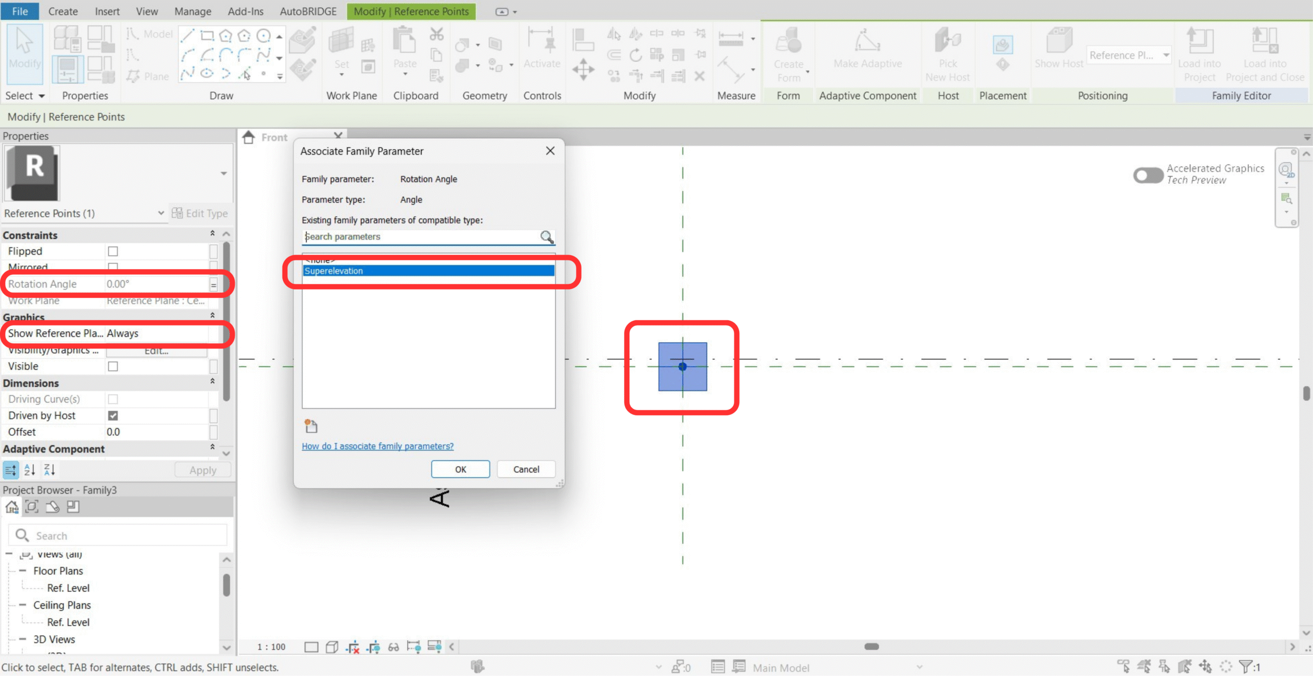
Associate Rotation to Superelevation Parameter
Select the adaptive point and set Show Reference Planes to Always. Then associate the rotation angle to the family parameter Superelevation. AutoBRIDGE will drive this parameter from the Civil 3D or corridor data during creation.
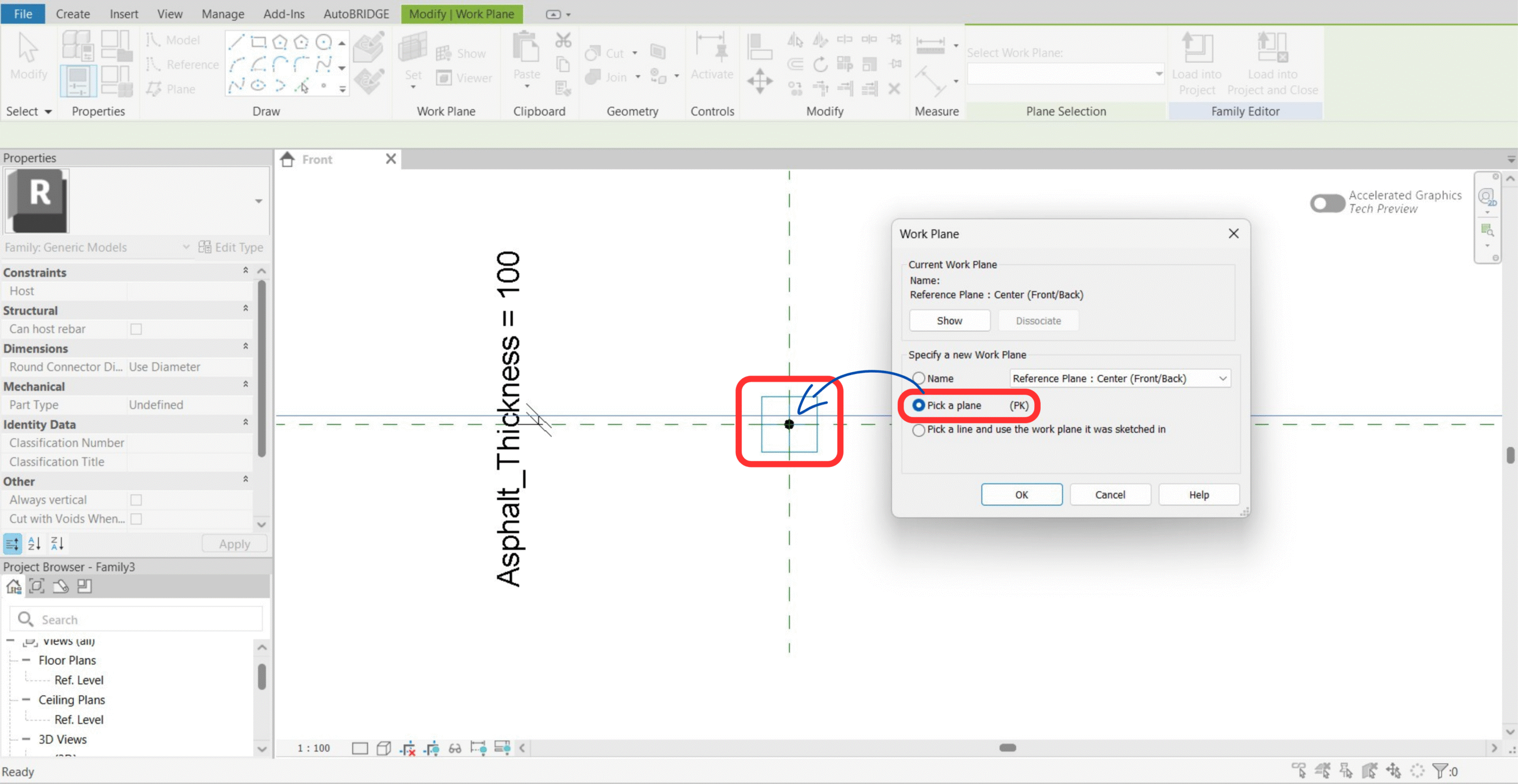
Set Work Plane to the Adaptive Point Surface
Use Set Work Plane → Pick a Plane and click the surface of the adaptive point. All subsequent geometry must be drawn on this plane to inherit the rotation correctly.
Geometry Creation & Rotation Test
Draw the cross-section reference lines and attach instance parameters for all key dimensions. Then test that the superelevation rotation works before adding the boundary splines.
Create Reference Lines & Dimension Parameters
Draw reference lines to define the section outline — for example a box girder shape. Add instance parameters for each key dimension: Right, Left, Depth, and any other corridor dimension required. Remember: no formulas, Instance only.
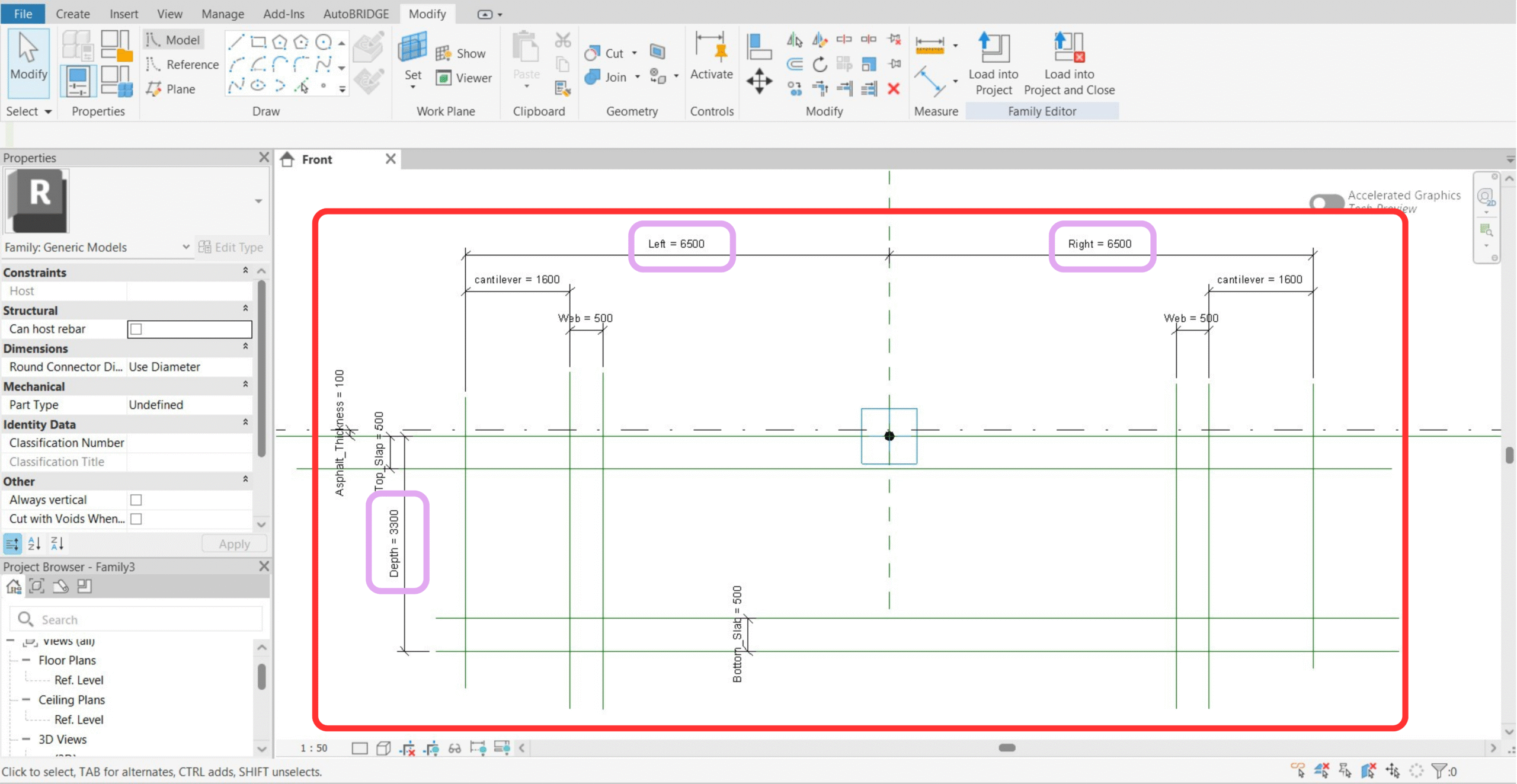
- Every parameter must be Instance — not Type.
- The formula column must be completely empty for all parameters. No formulas of any kind.
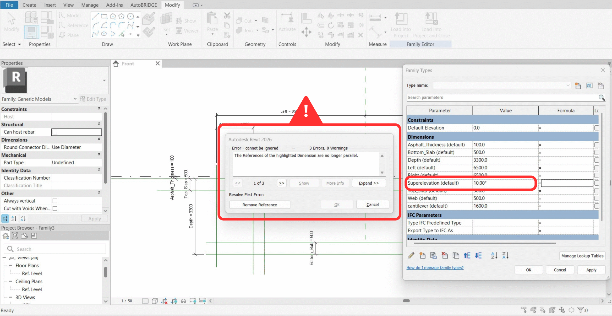
Test Superelevation Rotation
Enter a value in the Superelevation parameter and verify the entire section rotates correctly around the adaptive point. If an error appears, dimensions are constrained to non-rotating reference planes — remove the incorrect constraints and reapply them to the adaptive point's work plane.
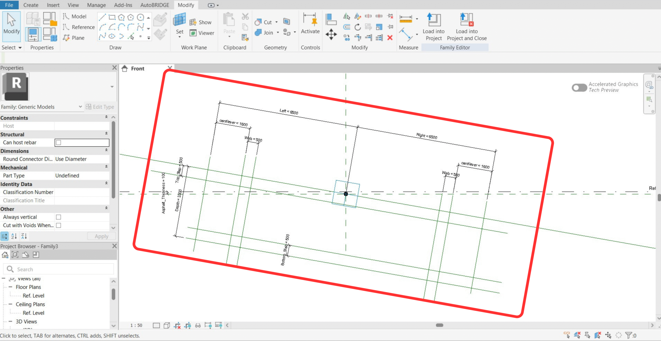
Rotation Success — All Geometry Rotates Correctly
When set up correctly, the entire cross-section rotates smoothly with the Superelevation parameter. Reset to 0 before continuing to the boundary phase.
Boundaries & Subcategories
Draw the outer (solid) and inner (void) boundary splines through the reference line endpoints, create named subcategories in Object Styles, then assign each subcategory to the correct boundary. AutoBRIDGE reads these subcategory assignments to determine which geometry is structural material and which is a void cut.
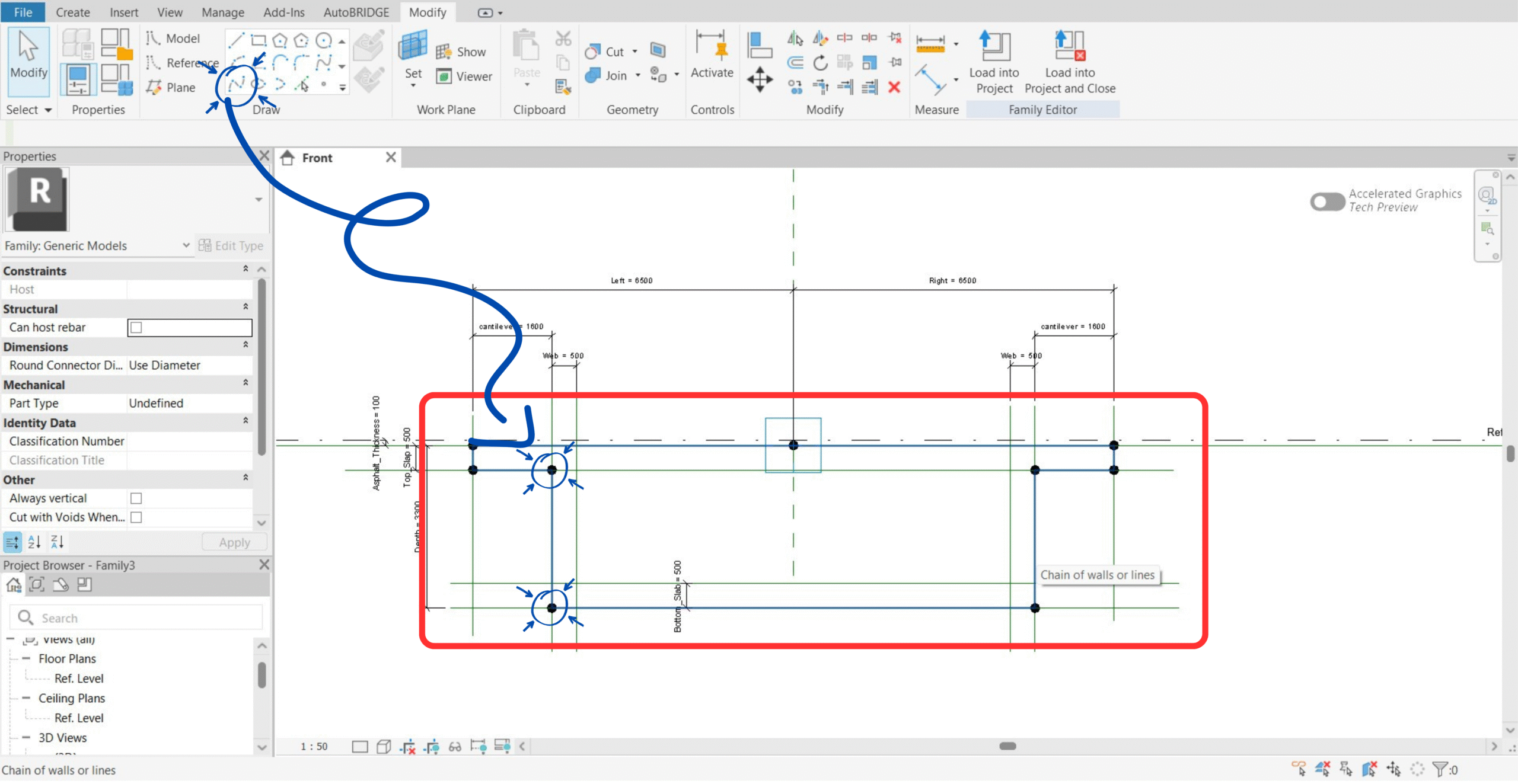
Reset Rotation & Draw Boundary Splines
Set Superelevation back to 0. Draw a Model Spline through the outer boundary points (deck extents) and a separate spline through the inner boundary points (hollow void). Each closed loop becomes one subcategory.
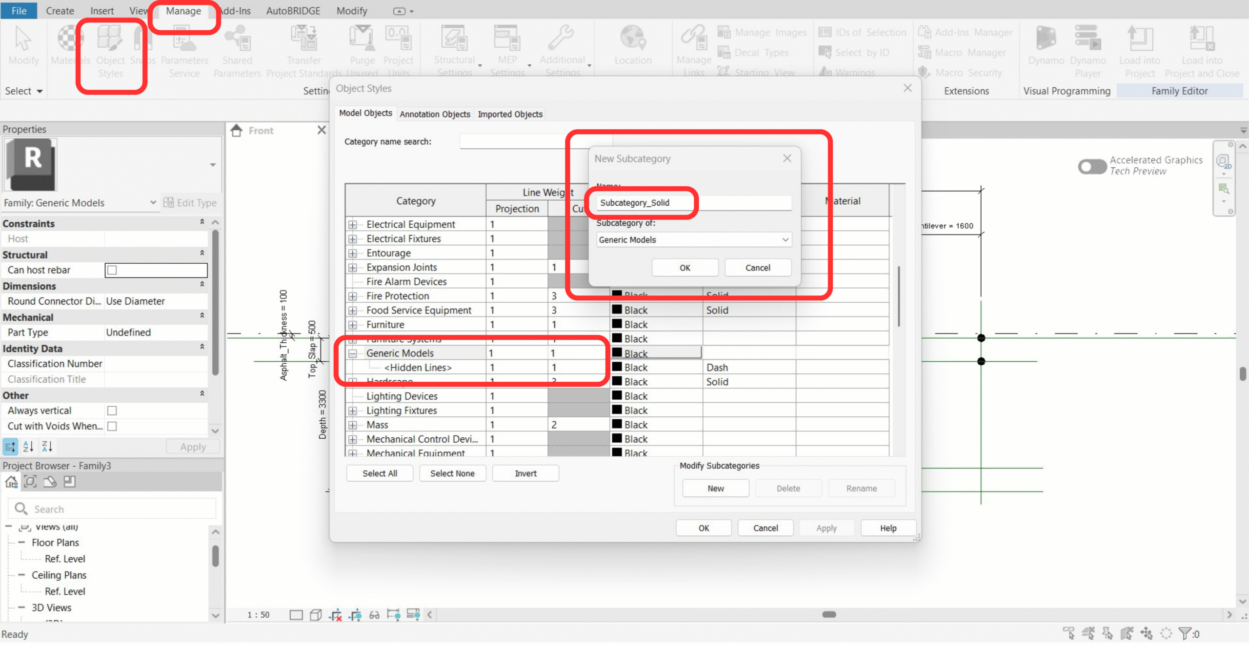
Create Subcategories in Object Styles
Go to Manage → Object Styles → Generic Models. Click New to create two subcategories — one for the solid outline (e.g. Deck_Solid) and one for the void (e.g. Void_Box). The exact names will be shown in AutoBRIDGE's family selector.
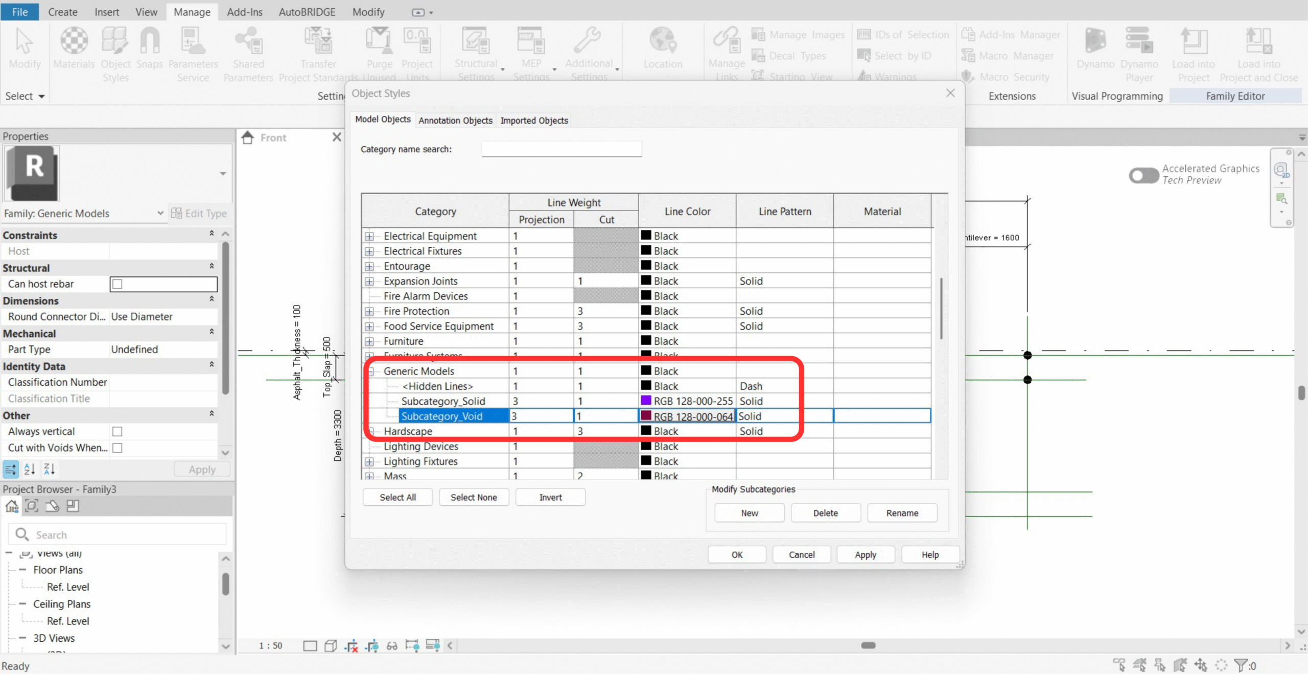
Verify Both Subcategories Are Created
Confirm both subcategories appear in the Object Styles list before proceeding. The colour assigned here will be the colour used in AutoBRIDGE's 2D section preview.
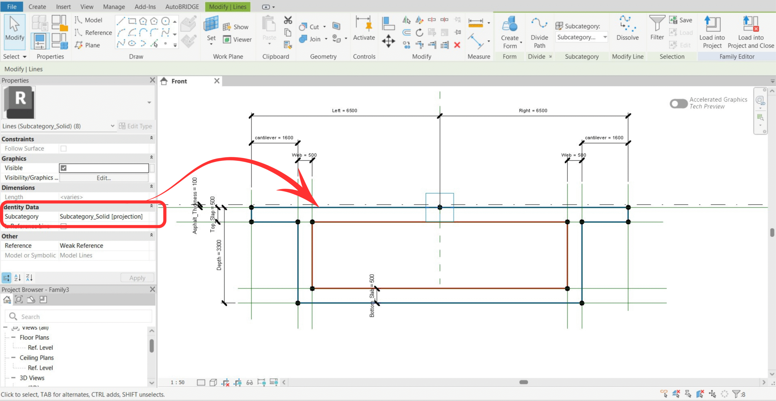
Assign Subcategories to Boundaries
Select the outer boundary spline → Properties → Subcategory → assign the Solid subcategory. Select the inner boundary spline → assign the Void subcategory. Save the family with a unique name.
AutoBRIDGE Family Manager
Register the completed nested family in AutoBRIDGE's Family Manager. This makes it available as a cross-section option in all corridor creation methods.
Watch the full Family Manager walkthrough for a live demonstration of all steps in this phase.
Open AutoBRIDGE → Family Manager
Click the Family Manager button in the AutoBRIDGE ribbon tab. The interface opens with five zones: Nested Family Preview, Template Section, Nested Family List, Subcategory List, and the Current Template indicator.
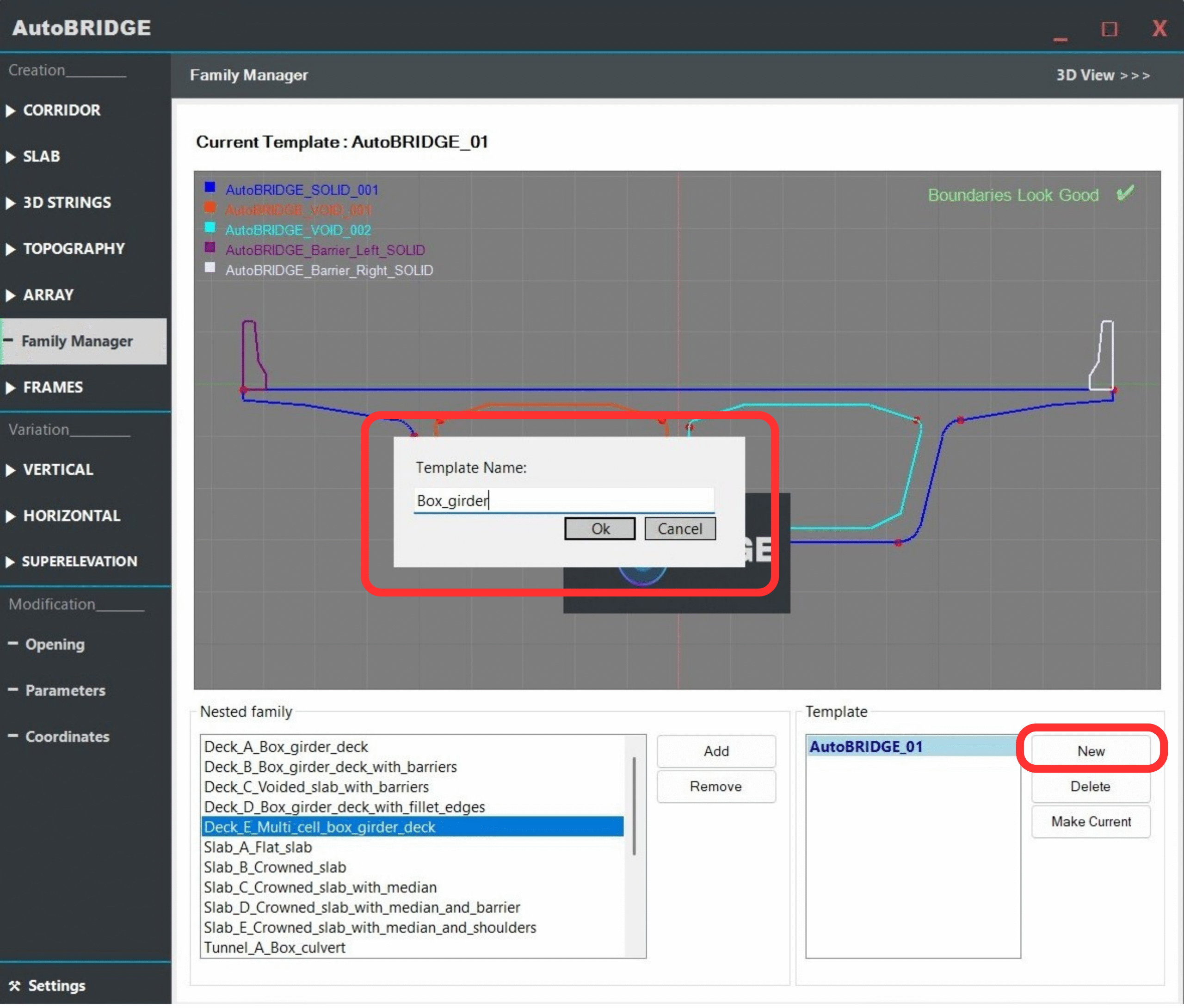
Create a New Template
In the Template Section, click New Template and enter a name that reflects the project or bridge type (e.g. BoxGirder_TwinCell_v1). Templates group nested families together for reuse across multiple corridors or projects.
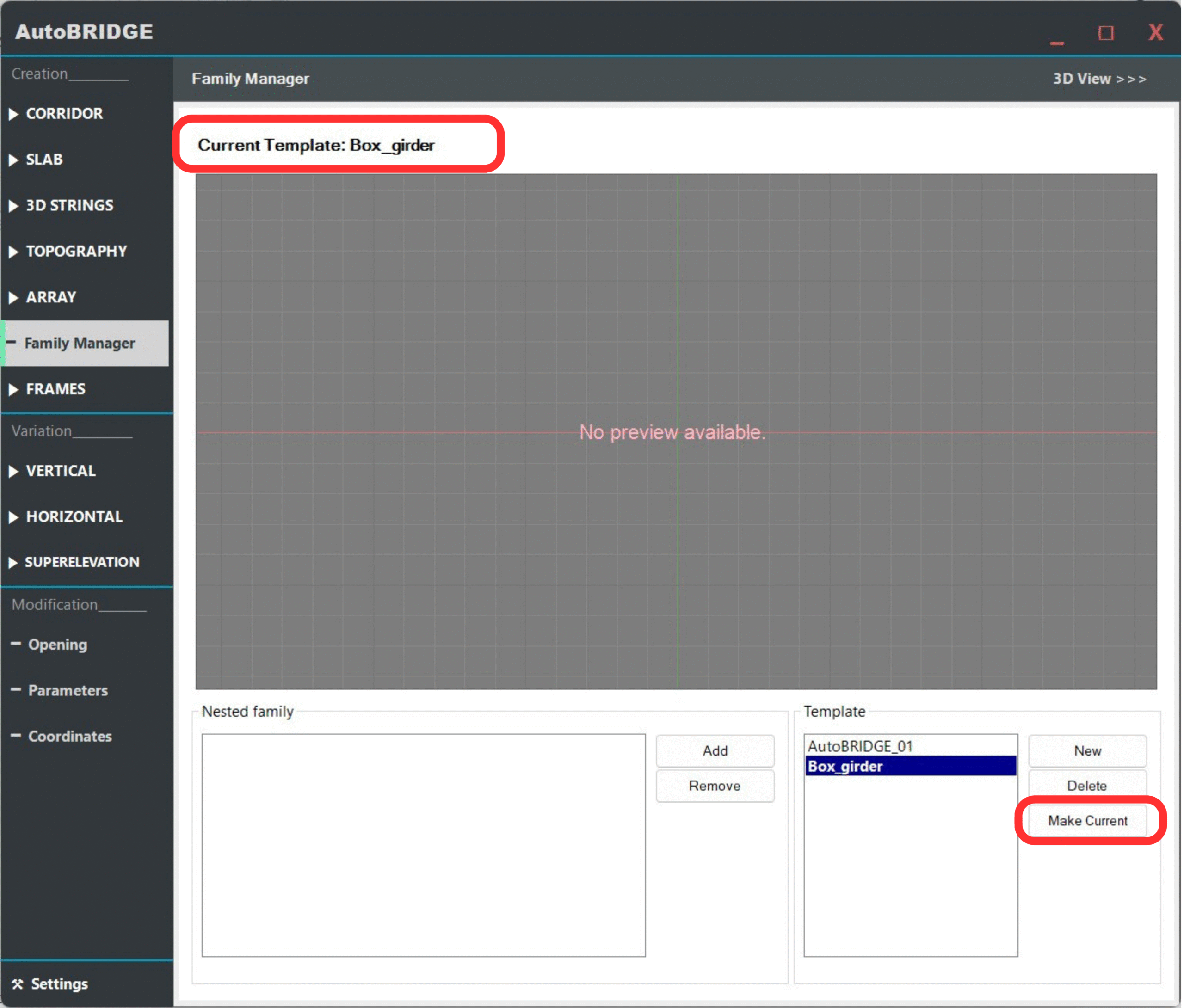
Set the Template as Current
Select the new template in the list and click Make Current. Only the current template is used during corridor creation — this step is essential before adding the nested family.
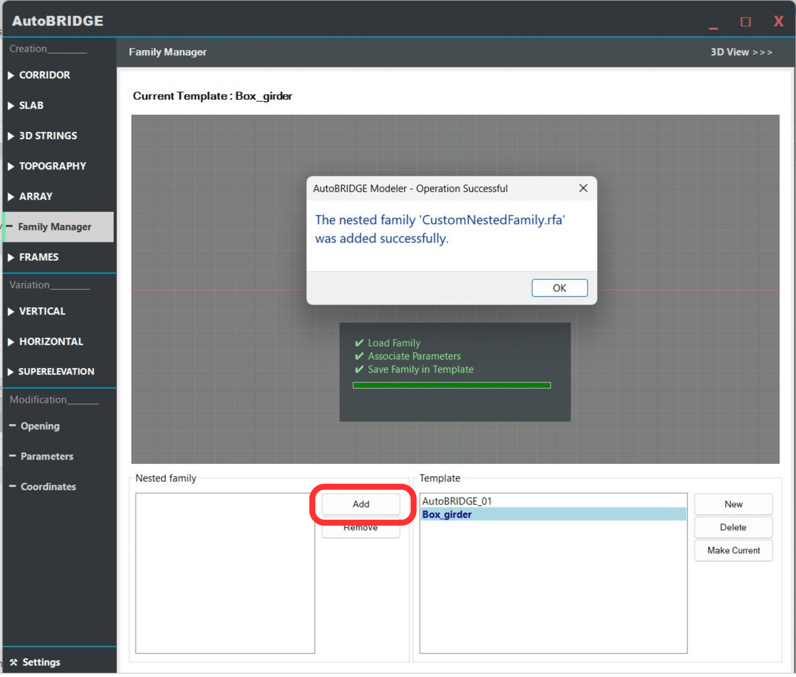
Add the Nested Family
Click Add in the Nested Family List and browse to your saved nested family .rfa file. AutoBRIDGE reads the family, validates its parameters and subcategories, then displays a success message.
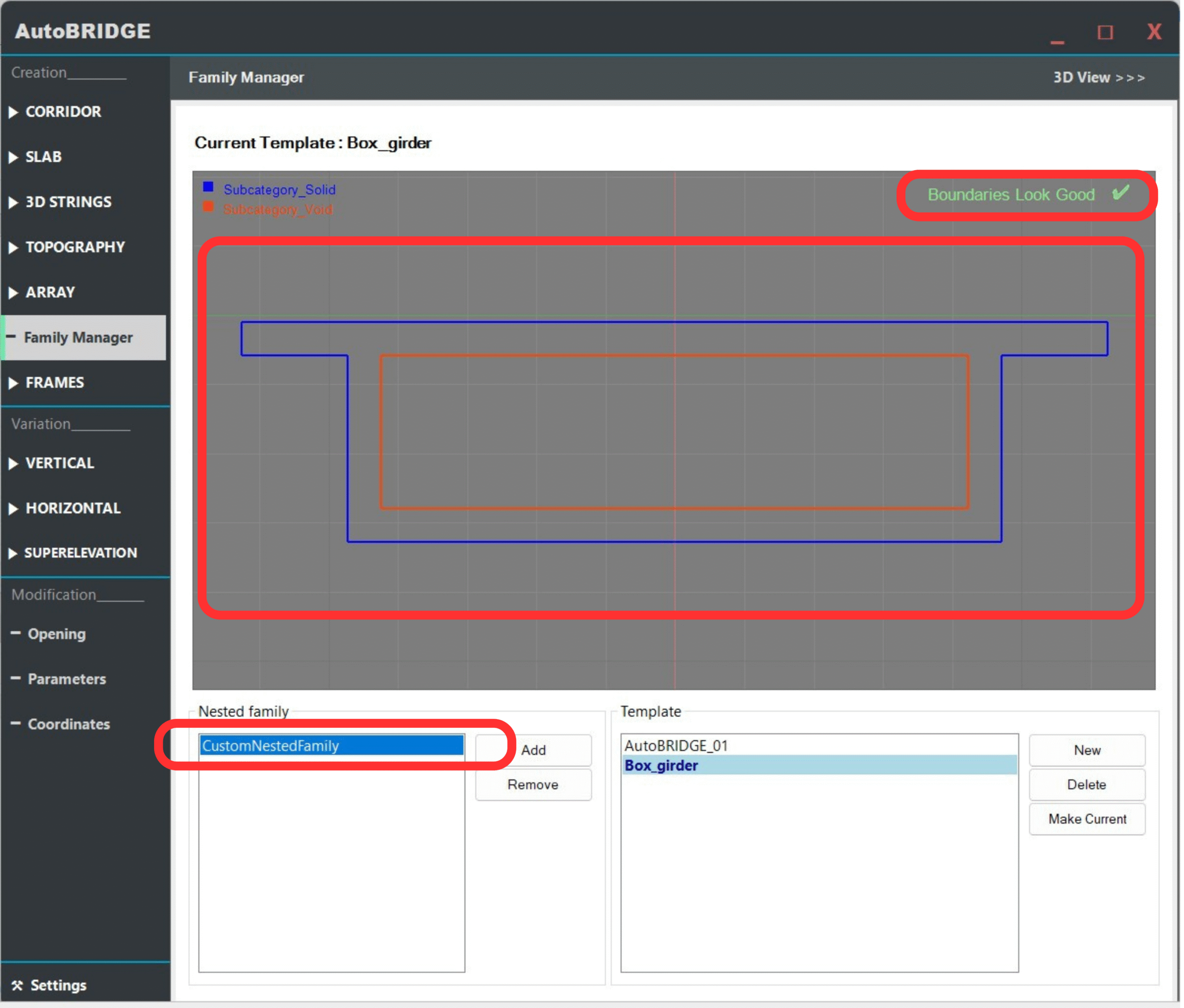
Verify the Nested Family Appears in the List
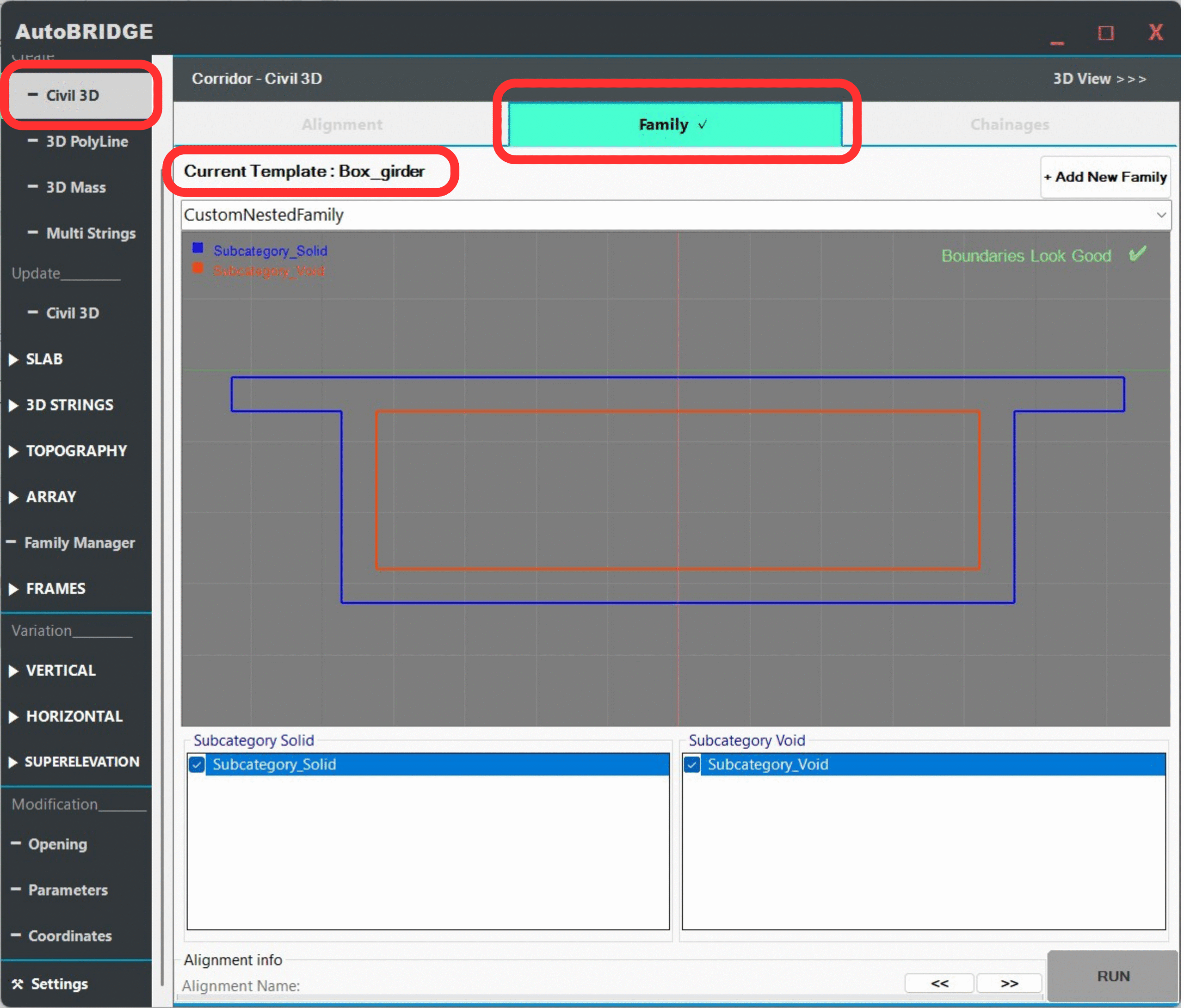
Confirm the nested family name appears in the Nested Family List and the subcategories (solid and void) are shown in the Subcategory List. The 2D preview panel should display the cross-section outline colour-coded by subcategory.
Corridor Validation
Open any AutoBRIDGE corridor creation tool and confirm that the new template and nested family are correctly detected in the Family section. Then run a test corridor to validate the geometry end-to-end.
Confirm Family Appears in Corridor Creation
Open AutoBRIDGE → Corridor Creation (Civil 3D, 3D Polyline, or 3D Mass method). In the Family dropdown, confirm the current template name and your nested family are shown correctly.
For full corridor creation steps, see: Corridor Creation Workflow →
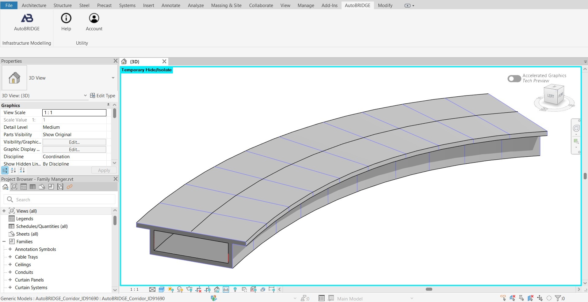
Corridor Generated Successfully
Run the corridor and verify the output. The cross-section geometry, superelevation rotation, solid extrusions, and void cuts should all appear correctly along the full corridor length.