
Setout Points & Coordinate Extraction
Embed coordinate markers into bridge corridor sections and export survey-ready data as a CSV or Revit Schedule — without any manual point picking.
What is Setout Point Extraction?
The Setout Points workflow embeds named coordinate markers directly into the nested corridor family. Once the corridor is generated, AutoBRIDGE reads the world coordinates of every marker at every station automatically — no manual point picking or schedule setup required.
The output can be exported as a CSV file for site engineers or added to a Revit Schedule for issue with construction drawings.
Named Points
Each marker type (e.g. Left Edge, Right Edge) is a named family type — consistently identified across all stations.
Automatic Extraction
AutoBRIDGE identifies all shared location families across the entire corridor in one operation.
CSV Export
Export all coordinates to a survey-ready CSV file, formatted for direct site use.
Revit Schedule
Optionally push coordinates into a Revit Schedule for inclusion in construction documentation.
The Location Family
The location family is a lightweight Generic Model Adaptive family that acts as a coordinate tracker. It has a simple identifying shape and must be marked as Shared so its instances can be scheduled independently inside the corridor.
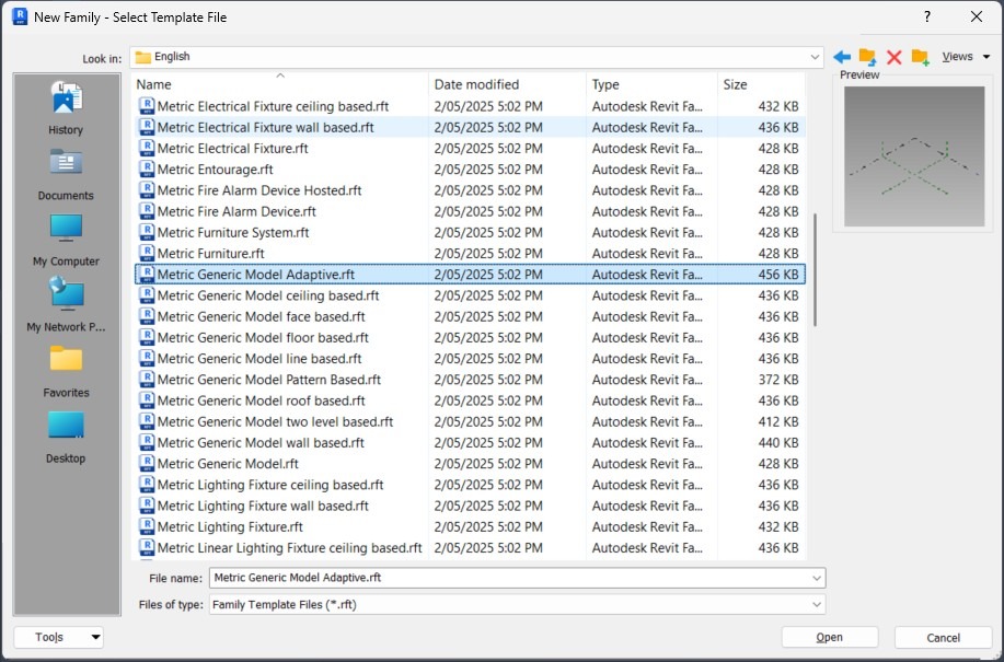
Create a Generic Model Adaptive Family
In Revit, go to File → New → Family and choose the Generic Model Adaptive template. This will be the location tracker family.
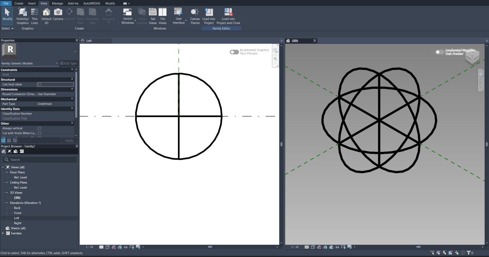
Add an Identifying Shape
Create a simple circle or small marker shape at the adaptive point origin. This makes the point visually identifiable when loaded into the main nested family and viewed in plan or 3D.
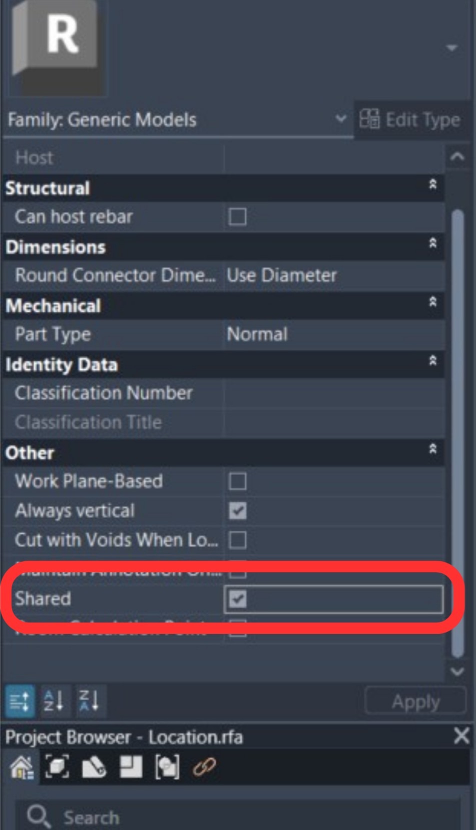
Enable the Shared Property
Go to Family Category and Parameters and check the Shared checkbox. This is essential — without it the family instances cannot be scheduled or extracted independently by AutoBRIDGE.
Nested Family Integration
Load the location family into your corridor nested family and configure a named type for each setout point position on the cross-section. Each named type becomes an independently extractable coordinate in the output.
Prepare the Nested Corridor Family
Open your corridor nested family or start from the AutoBRIDGE template. Load the Location Family into it using Insert → Load Family.
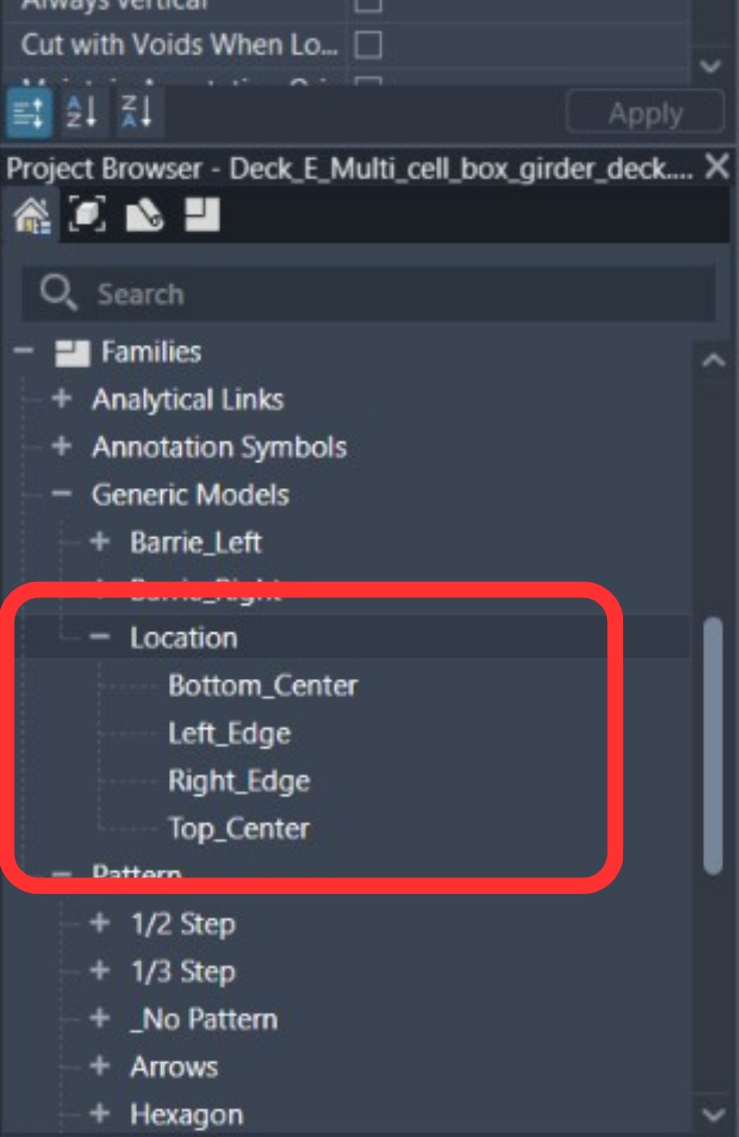
Duplicate Types for Each Point Name
In the Type Properties of the location family, duplicate the type for each named setout point you need. Common examples:
Right_EdgeLeft_EdgeTop_CenterBottom_Center
Each type name will appear as a distinct row in the exported coordinate table.
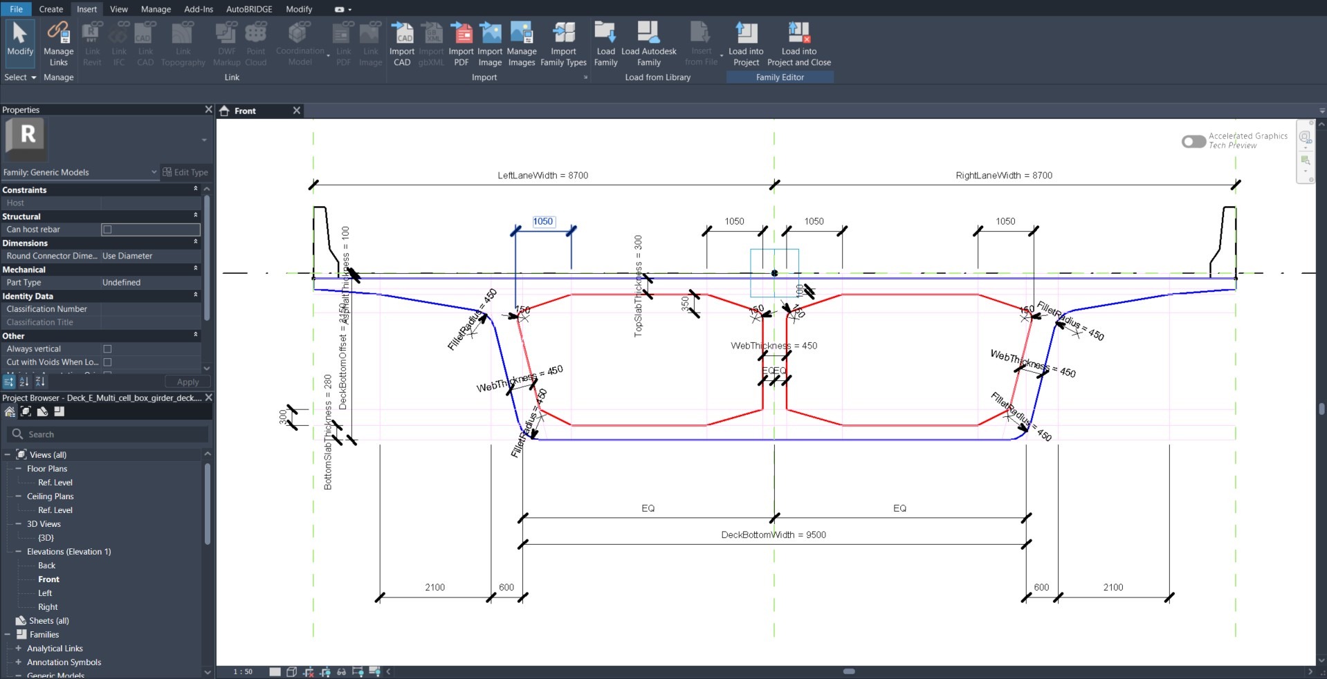
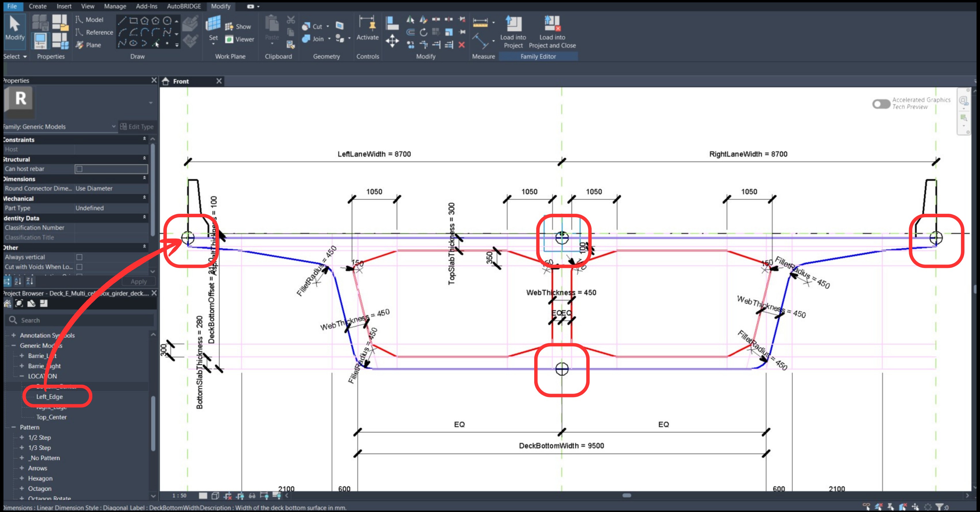
Place Each Point on the Section Geometry
Place each named location family type at its exact position on the nested family cross-section. Snap to geometry endpoints or use reference planes to ensure precision. Save the nested family with a new unique name.
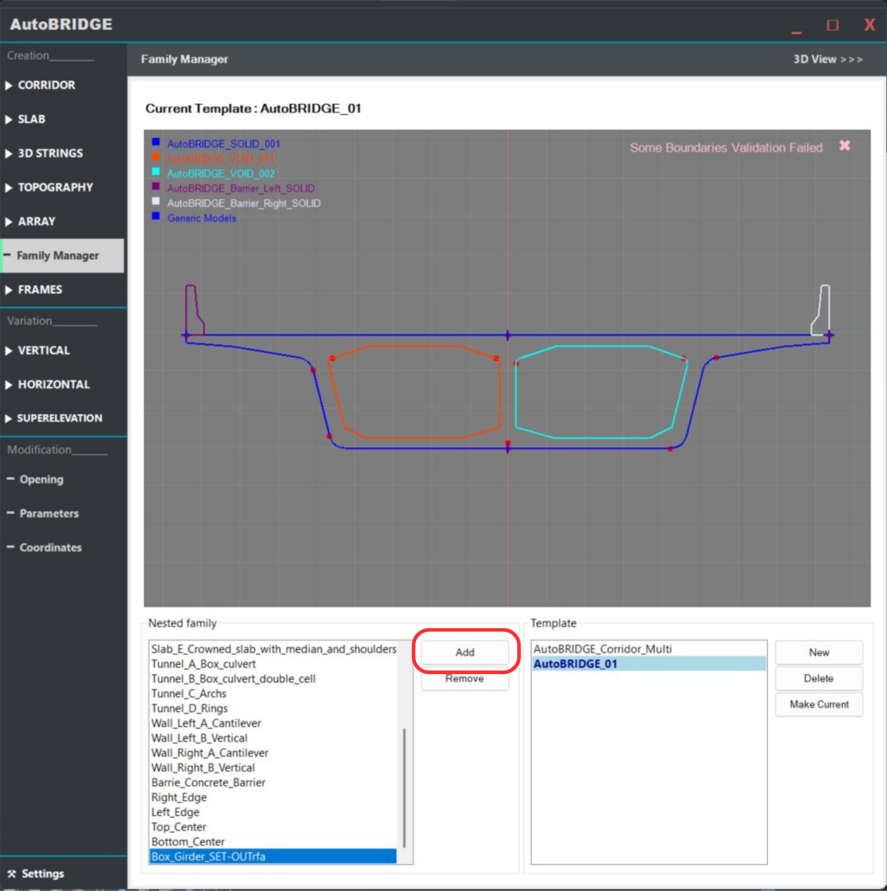
Register in AutoBRIDGE Family Manager
Open AutoBRIDGE → Family Manager and add your updated nested family to the active template. This makes it available for corridor creation.
Corridor Generation
With the nested family containing the named setout points registered, generate the corridor using any AutoBRIDGE corridor creation method. The location markers are embedded automatically at every station.
Run Corridor Creation
Open AutoBRIDGE and use any corridor creation method — Civil 3D, 3D Polyline, or 3D Mass — selecting the nested family that contains your setout point types.
See the full step-by-step guide: Corridor Creation Workflow →
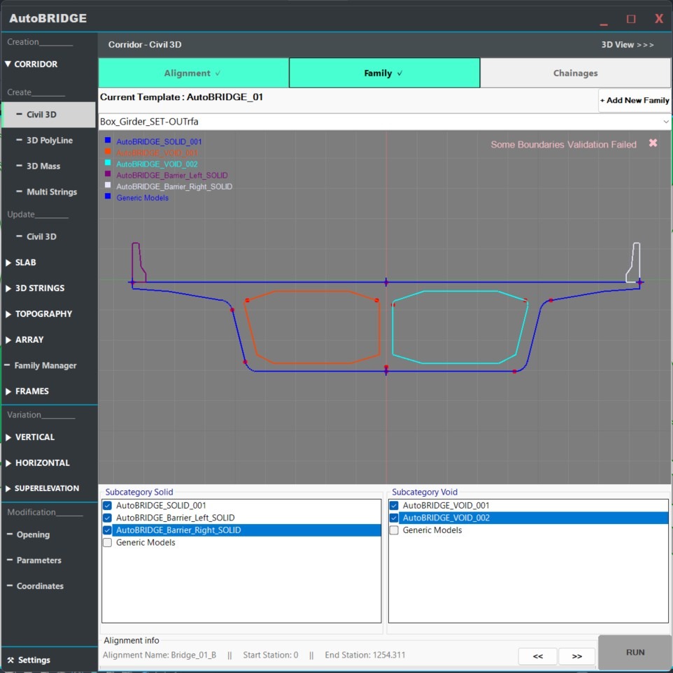
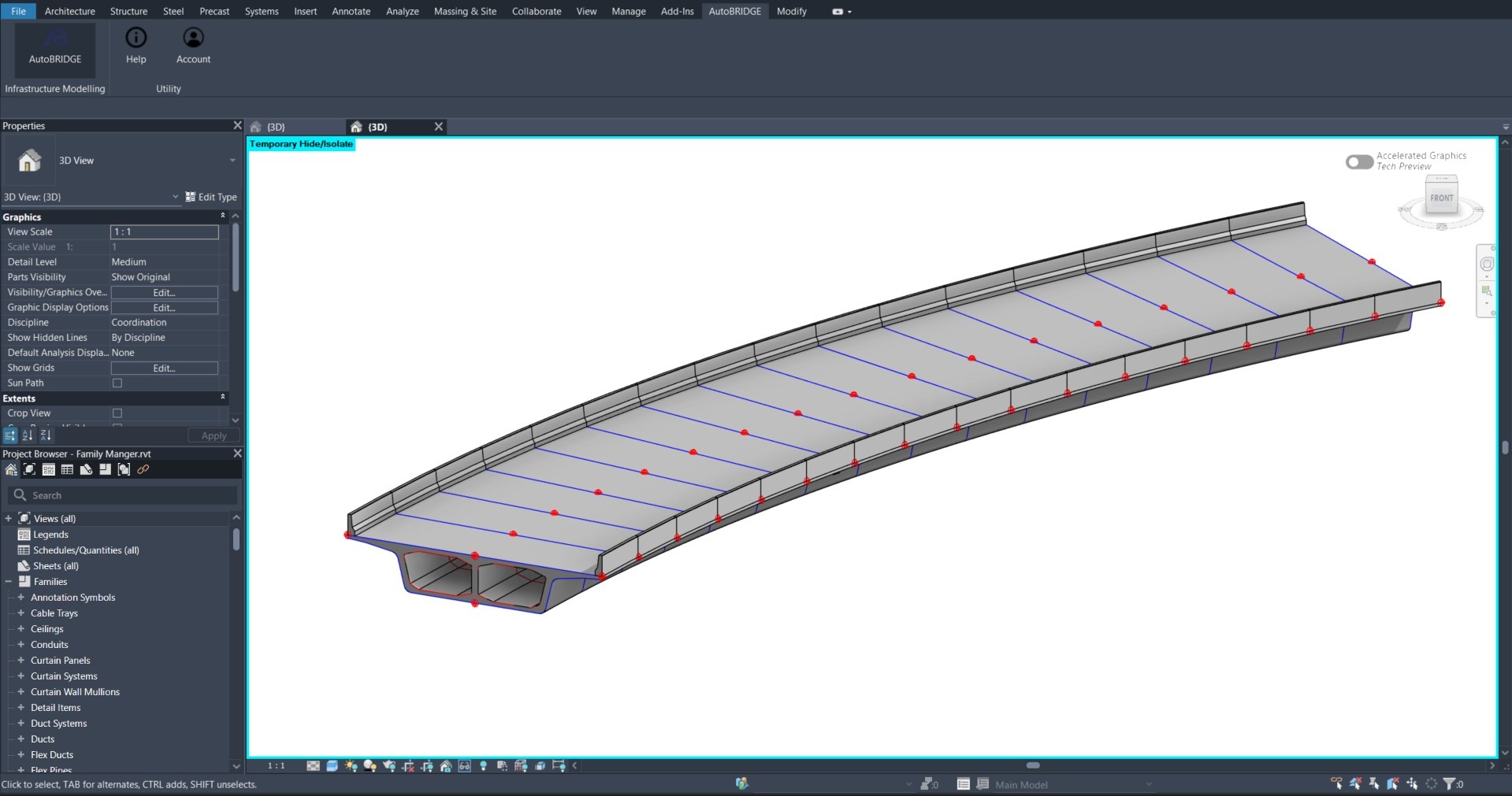
Corridor Generated Successfully
The corridor is created with all named setout point markers embedded at every section station. Each marker inherits the exact world coordinates of its position on the cross-section at that chainage.
Extraction & Documentation
With the corridor generated, use the AutoBRIDGE Coordinates tool to extract all point positions across all stations in a single operation, then export in the format needed for site or documentation use.
Open the Coordinates Tool
Go to AutoBRIDGE → Coordinates and select your corridor. The tool automatically scans all shared location family instances across the entire corridor and groups them by point name and station.
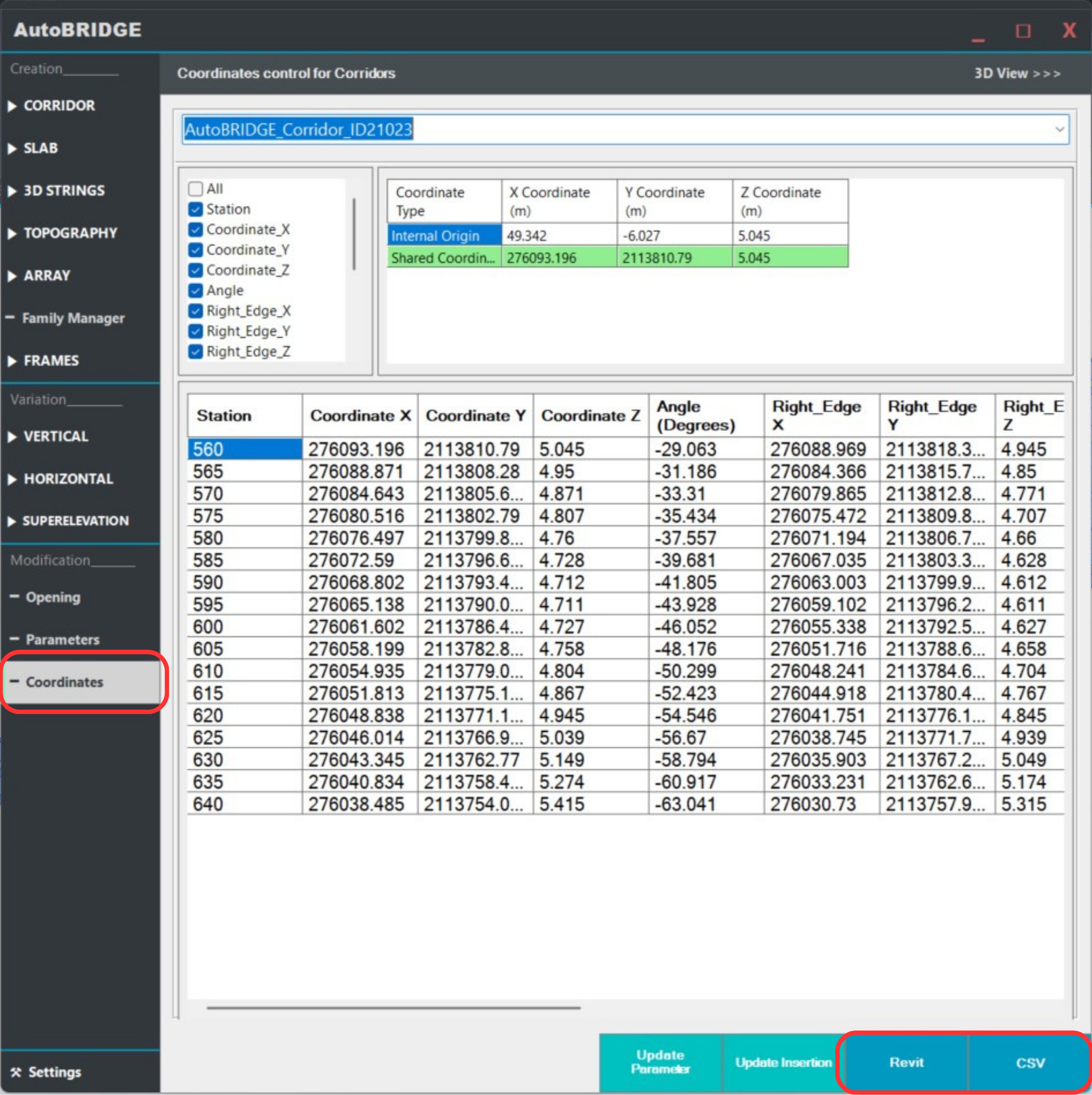
Export or Schedule
Choose your output format:
- CSV Export — generates a survey-ready file with point name, station, X, Y, Z for every instance across the corridor. Ready for site engineers and total station setout.
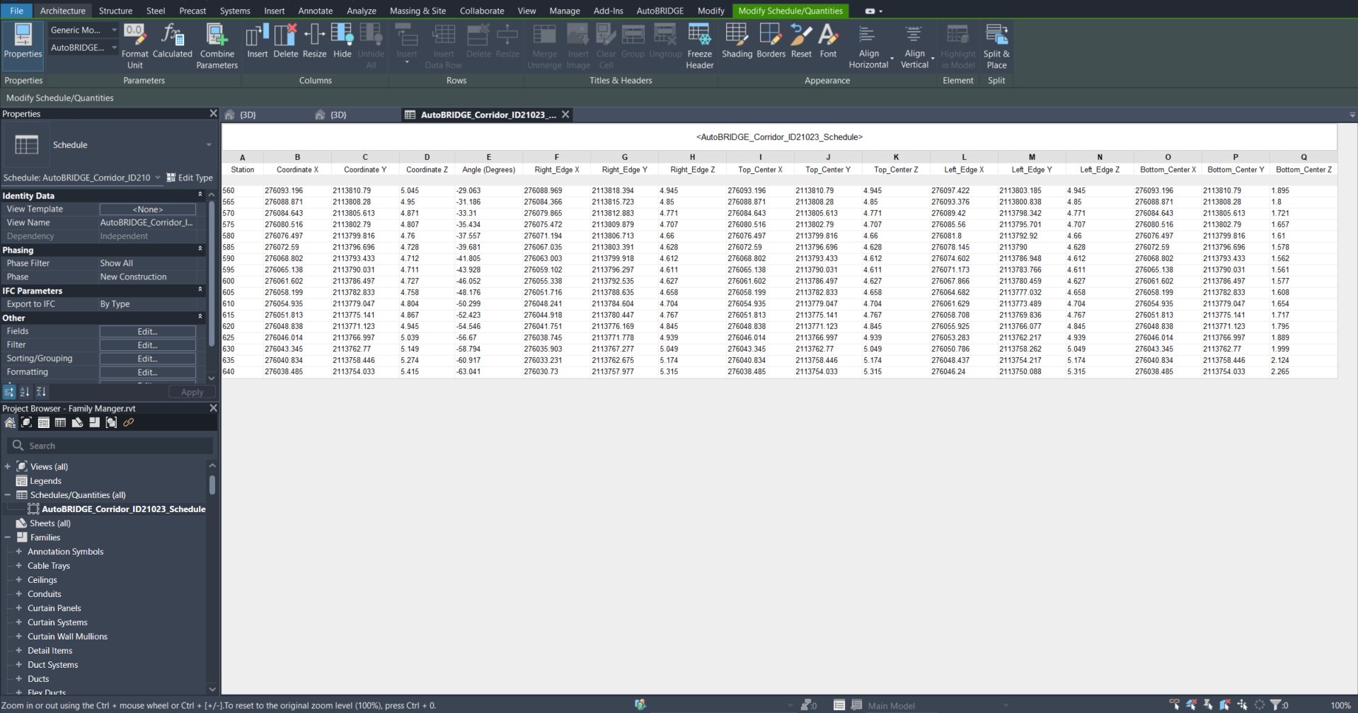
- Revit Schedule — pushes the coordinates into a Revit schedule for inclusion in construction documentation sets.
Deck_Left_Edge and Deck_Right_Edge rather than generic names. These names appear verbatim in the exported CSV and Revit schedule, making site reading much easier.